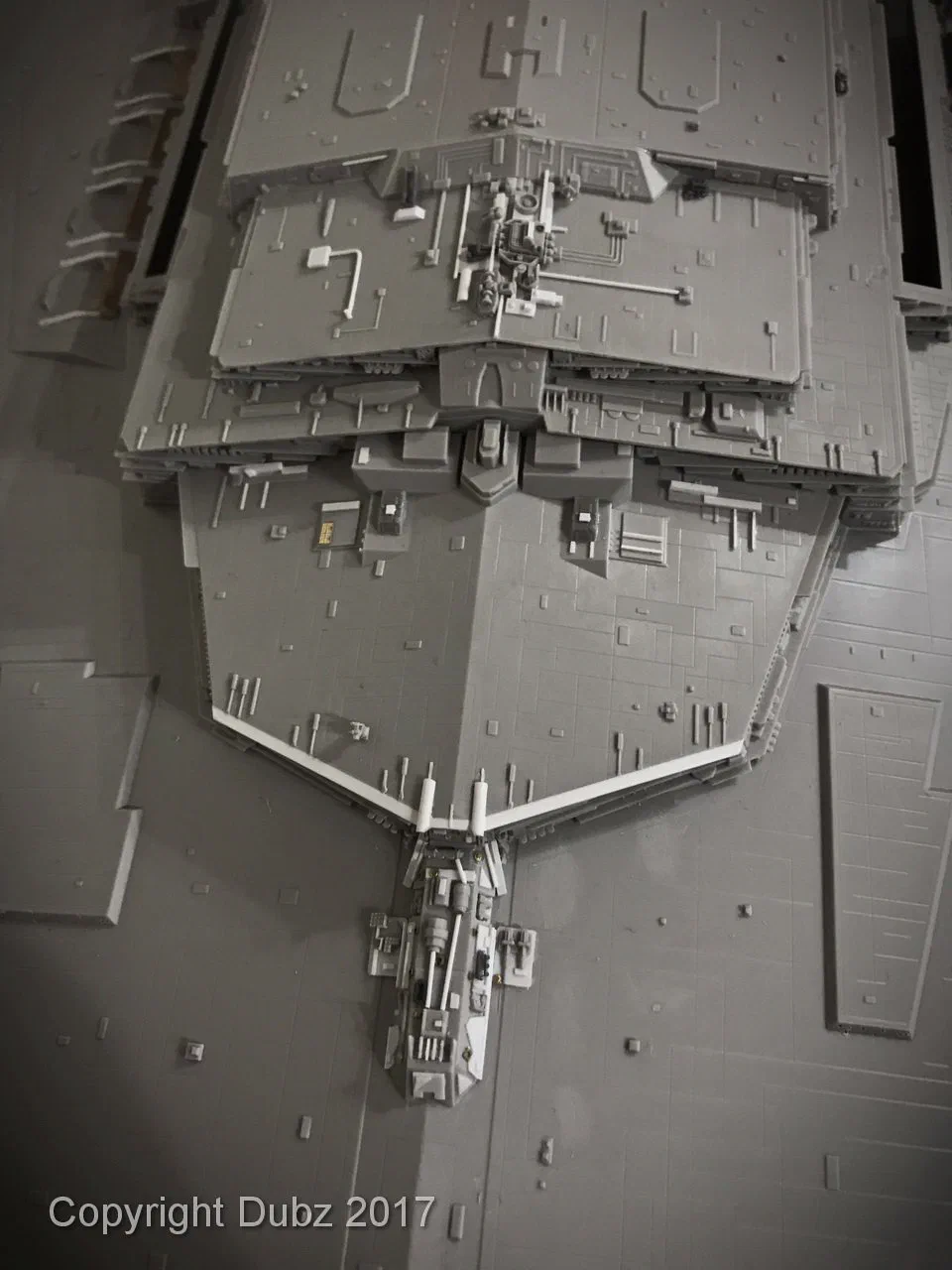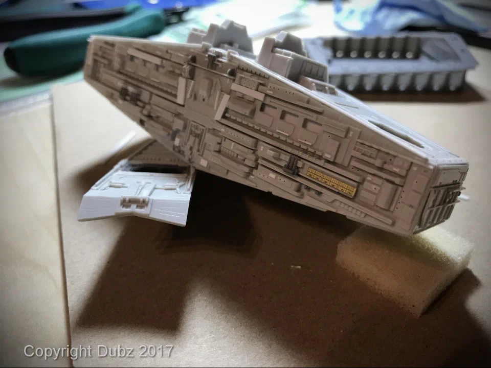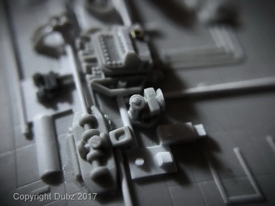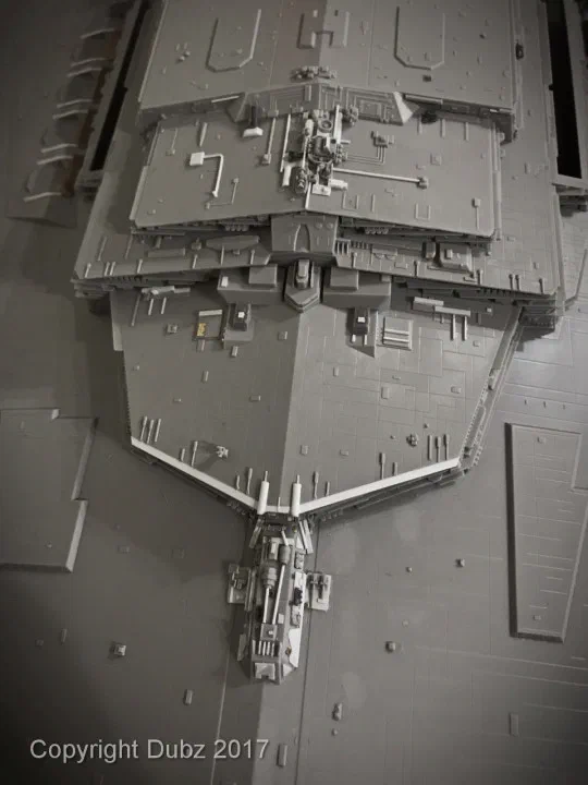
Work in progress

Imperial Star Destroyer – Zvezda 1:2700

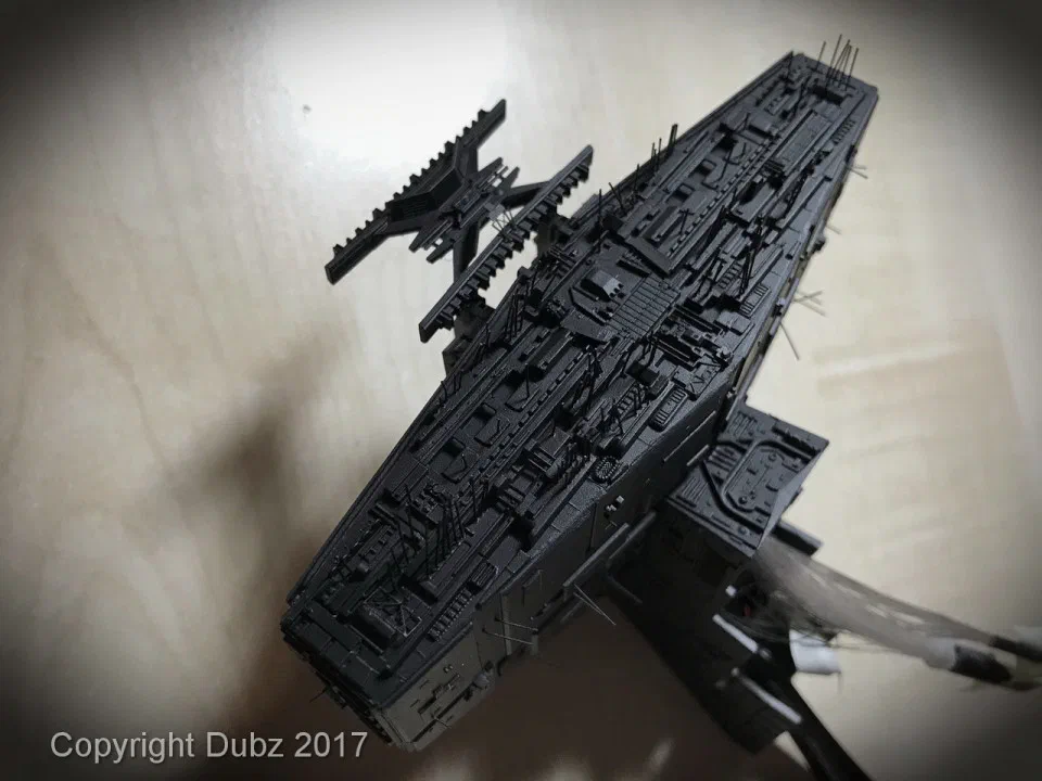
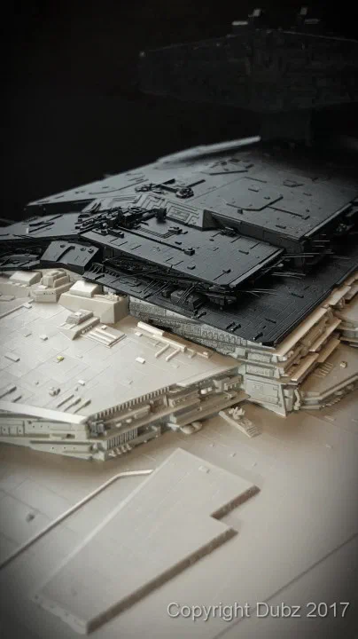
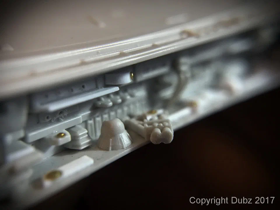
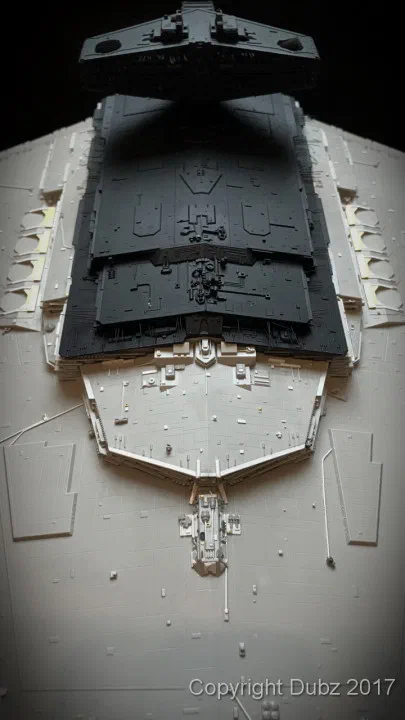
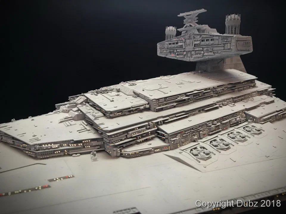
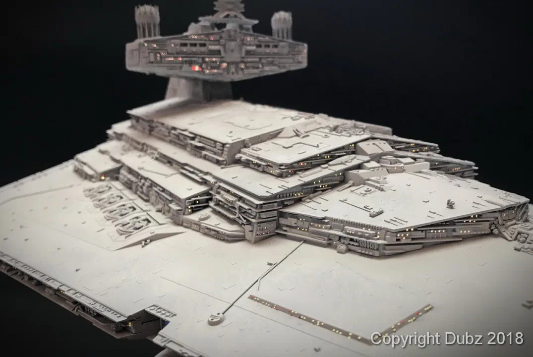
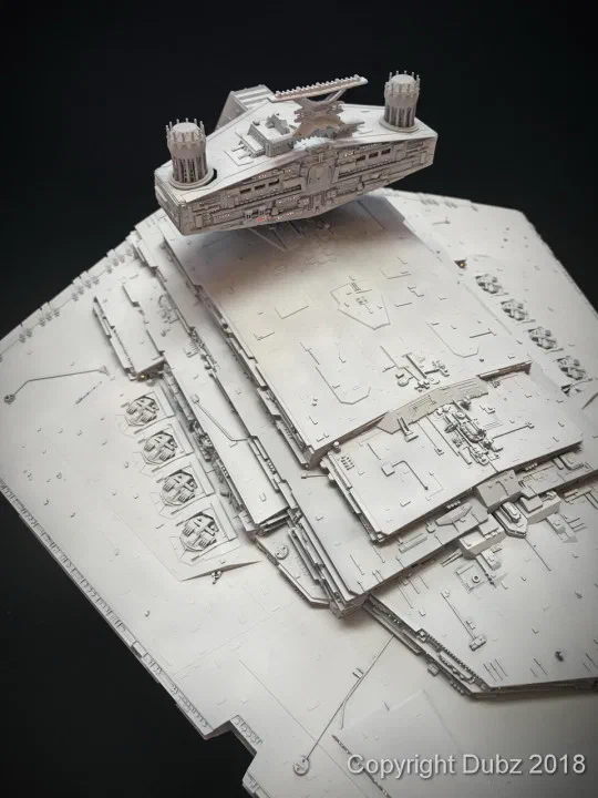
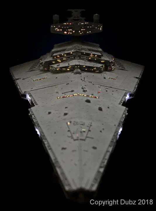
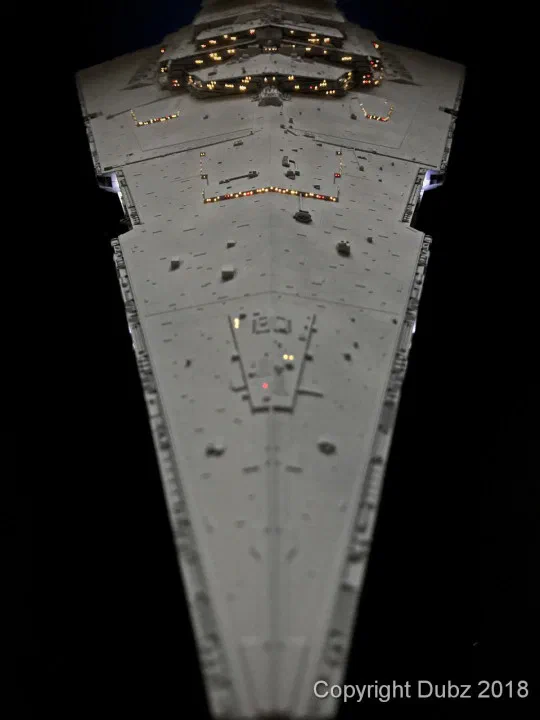
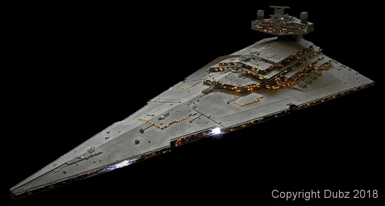
A Star Destroyer from the Zvezda kit – opened up, greebled, lit with around 200 metres of fibre optics and built into her own case. A lot of plastic, a lot of light, a lot of patience – and a lot of photos.

Imperial Star Destroyer – Zvezda 1:2700

A wedge full of detail

The Zvezda kit of the Imperial Star Destroyer is a big model with a good basic shape – and with a lot of room for more. My aim was not a slavish copy of one particular studio model. What I built is a combination: based on the studio model, inspired by the work of Invar, and with a good portion of my own imagination. Reference pictures served as orientation, but I was not dogmatic about them.
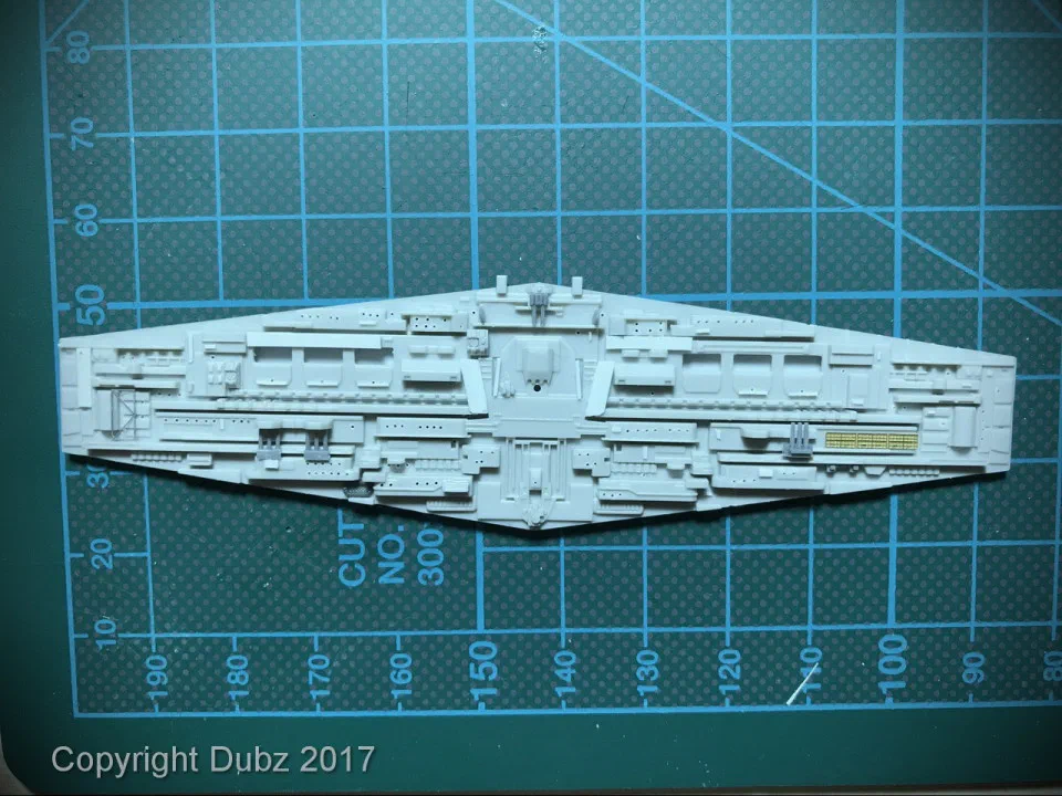
The Zvezda hull parts laid out on the cutting mat
The starting point: the Zvezda hull on the cutting mat.

At 1:2700 everything is tiny. A 3D-printed freighter of the right scale fits on a fingertip and shows how big the real thing would be.
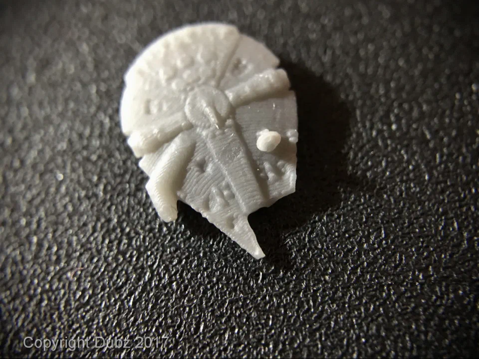
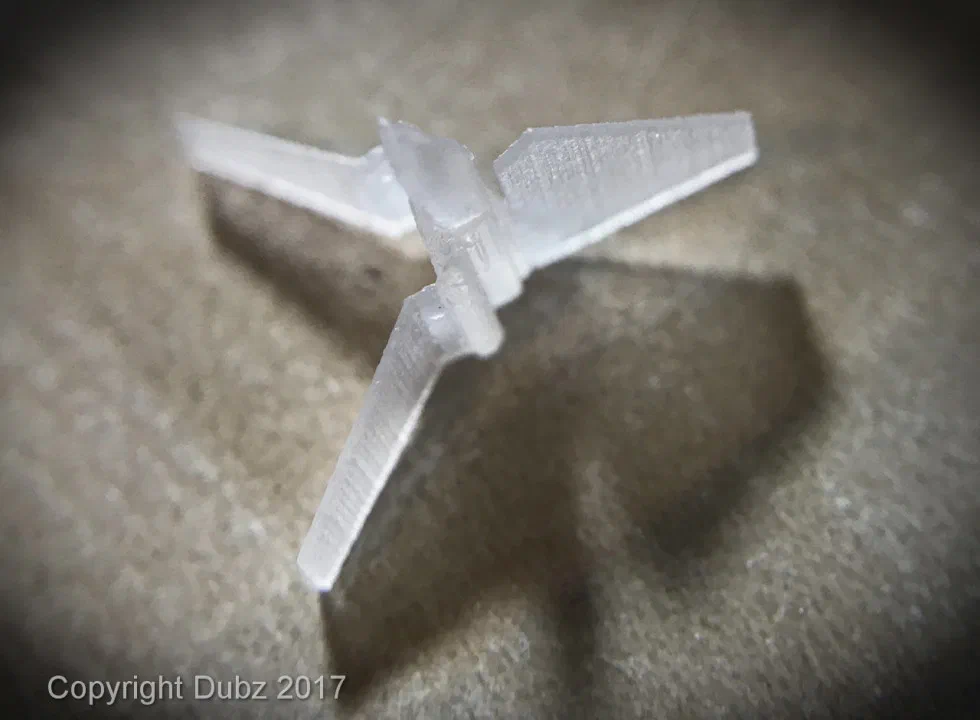
A tiny printed freighter in 1:2700 A tiny printed shuttle in 1:2700
1:2700 in one picture.

The bridge

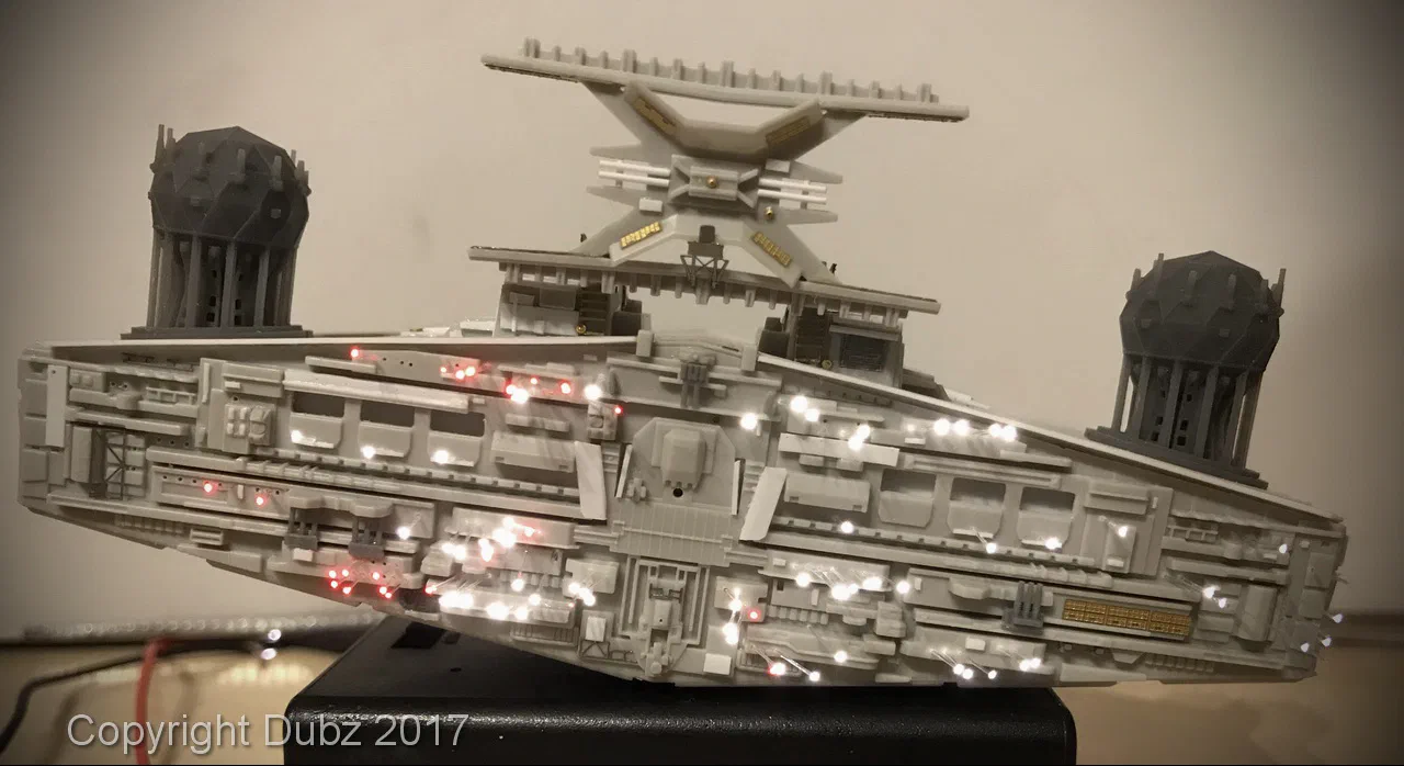
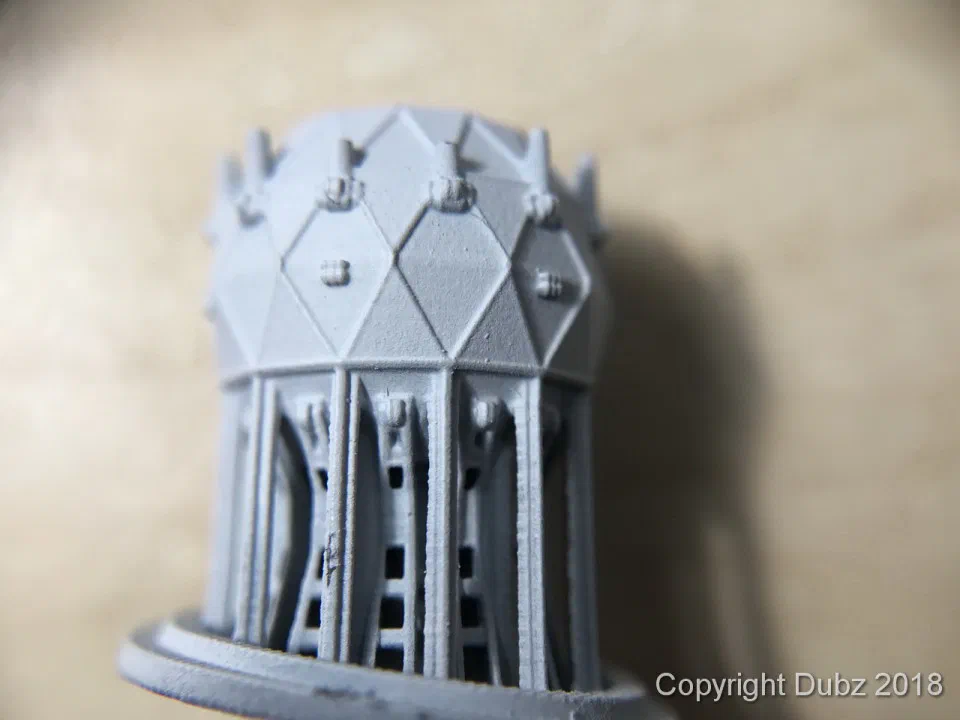
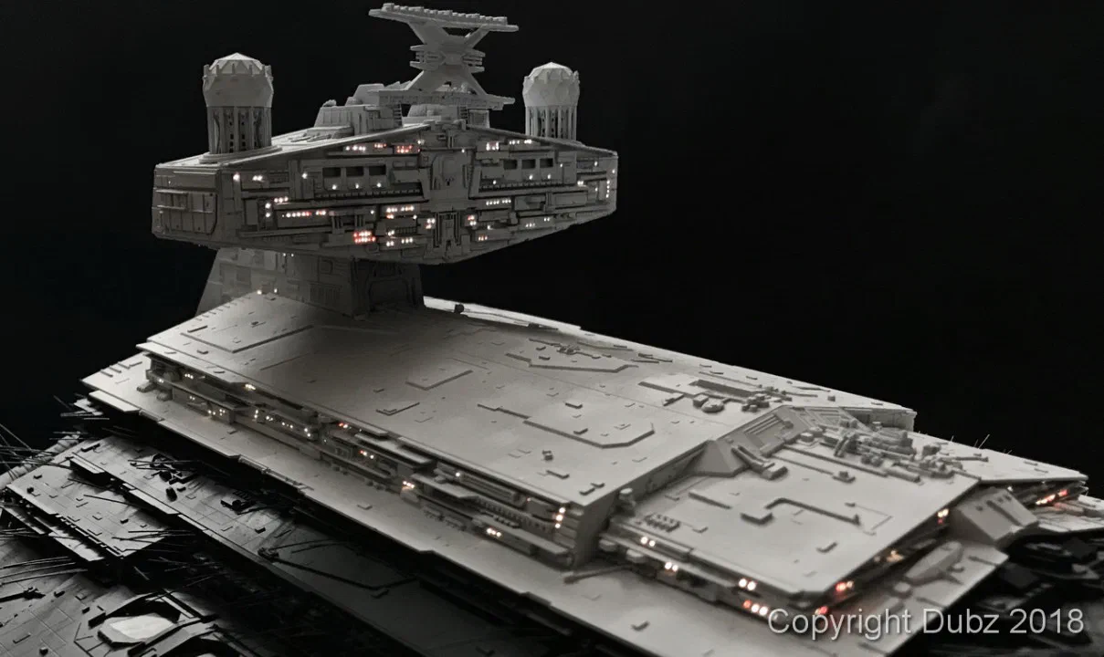
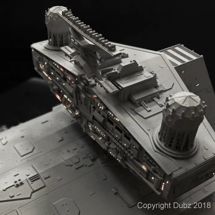
The build started at the top, with the bridge tower, which was prepared for lighting right from the start so that the windows would glow later. Not everything on top is styrene from the box or the spares drawer: the two shield generator domes are 3D-printed parts by Tony of 308 Bits (then sold through Shapeways). The engines with their lighting, the main hangar and the garbage chute come from the Falcon3D upgrade parts for the Zvezda Star Destroyer. Both Tony and Gus of Falcon3D were a real pleasure to deal with – very friendly, helpful and always ready to answer a question.
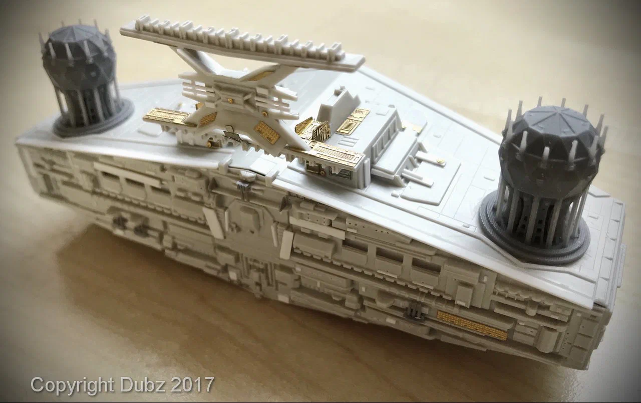
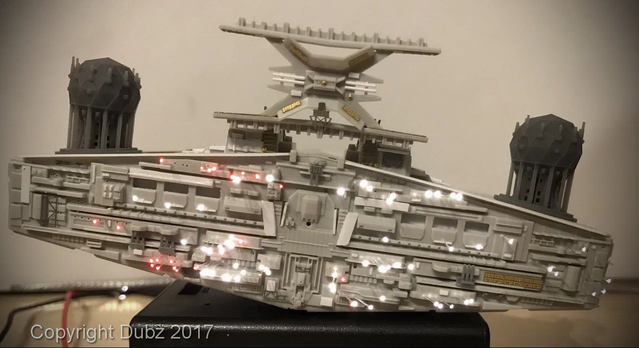
The bridge tower with added structure The bridge with its first lighting
The bridge – and the first light behind its windows.

The bridge tower grew layer by layer. Most of the additional structure is styrene and parts from the spares box; some parts came as 3D prints.
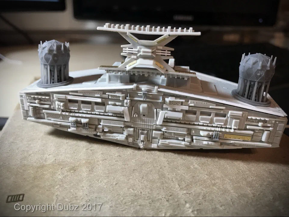
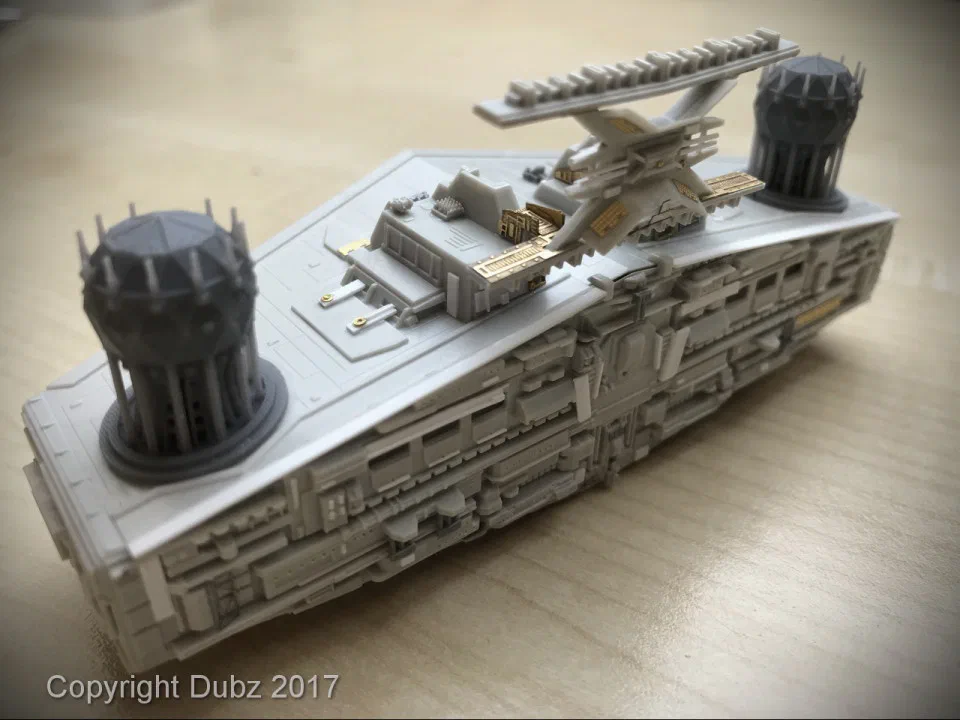
The bridge tower with added structure The bridge tower from the side
The bridge tower grows.
The upper superstructure with the bridge A 3D-printed tower part
Superstructure and bridge – and one of the printed parts.

Every window was drilled and tested with light long before the paint went on.
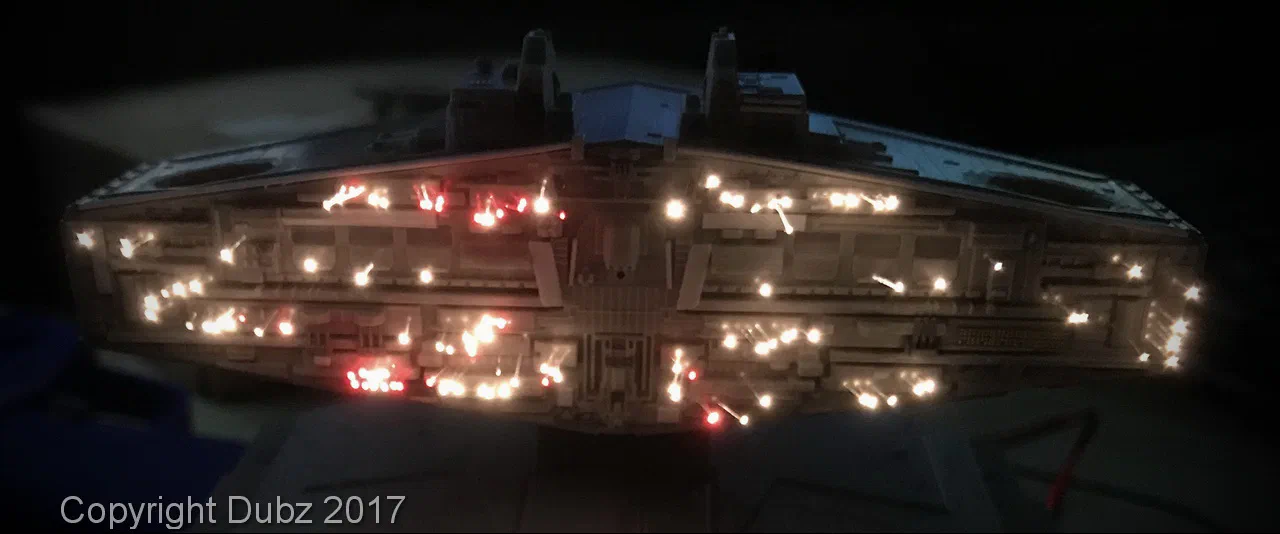
First light test in the dark Detail of the drilled superstructure
An early light test, and the drilled superstructure.

Modifying the hull

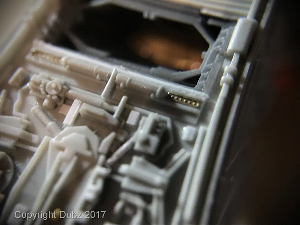
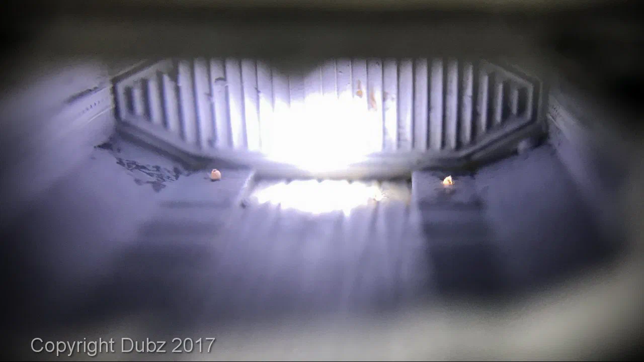
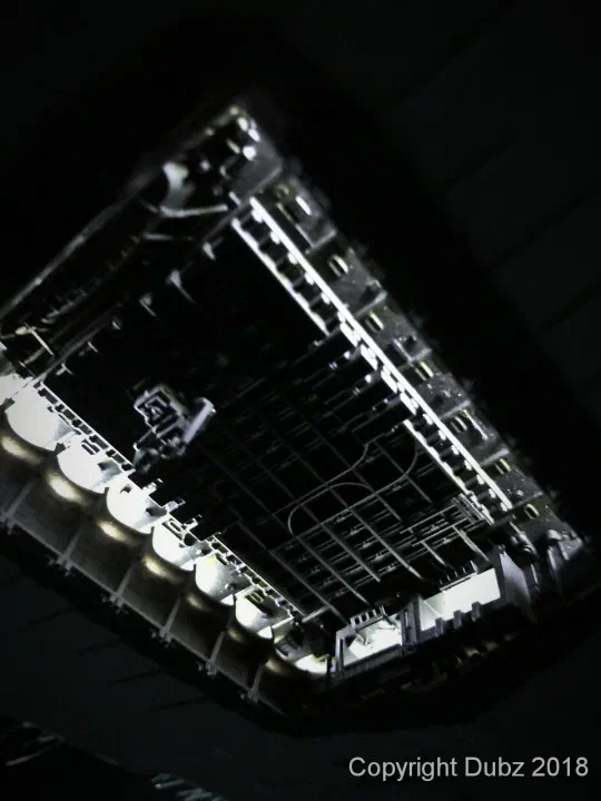
Some of the kit parts needed correcting before the detailing could start – one part, for example, simply had the wrong height. The trench hangar was opened up, and the garbage chute under the hull – a Falcon3D part – got its interior: it is greebled and lit inside, so that light falls out of the openings.
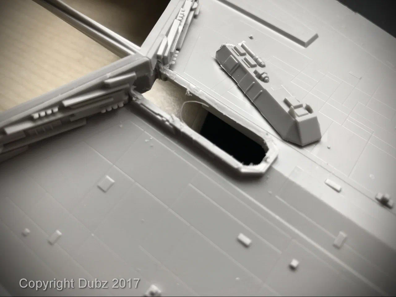
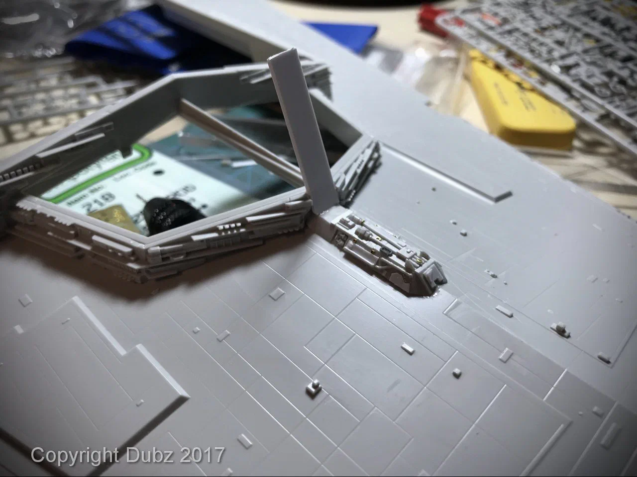
Correcting a part with the wrong height The opened trench hangar
Correcting the height of a part, and the opened trench hangar.
The lit garbage chute from below Light falling from the garbage chute
The garbage chute – detailed and lit from inside.
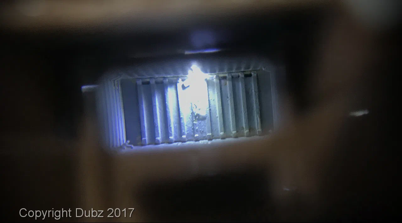
The lit interior seen through an opening Bright light inside the hull
Light inside the hull.

Hangar bay and guns

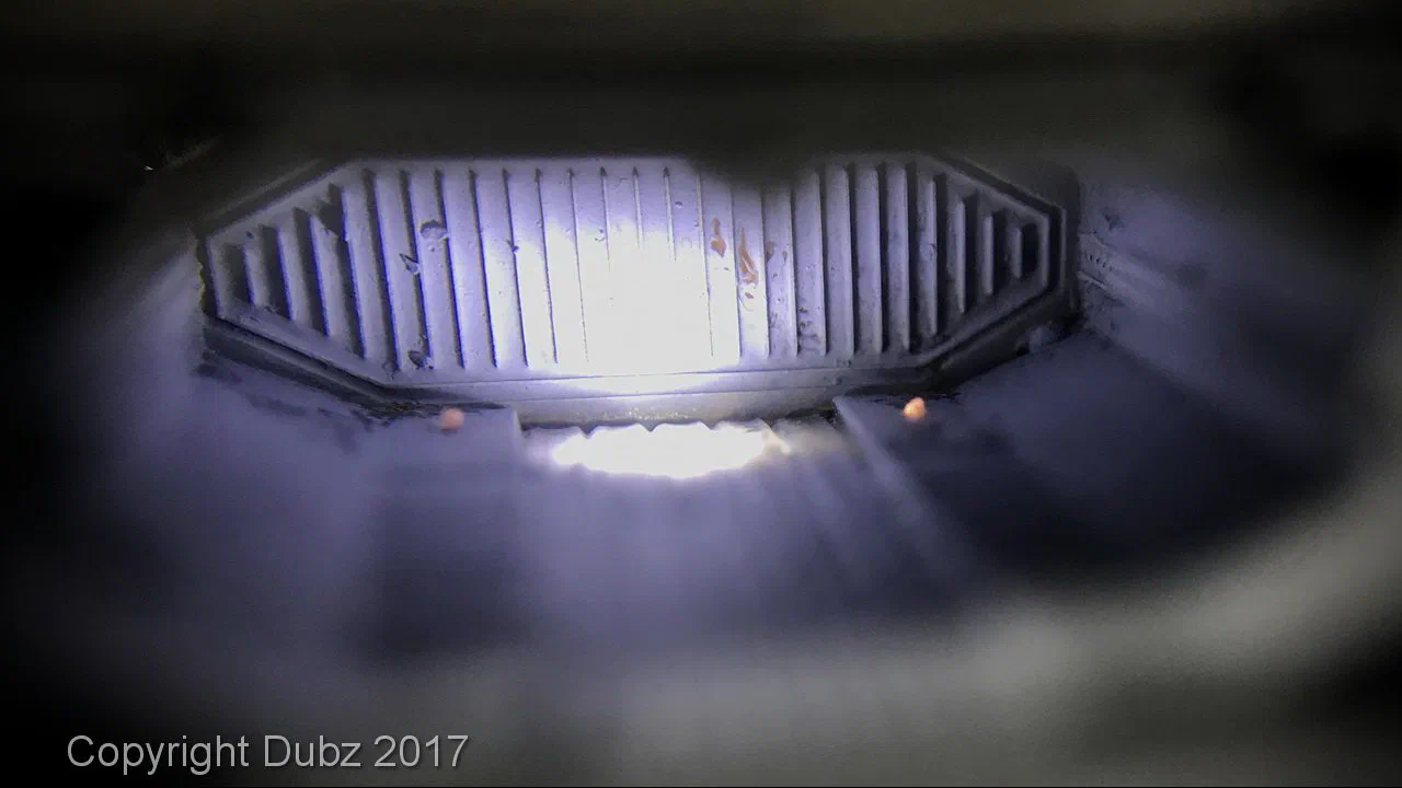
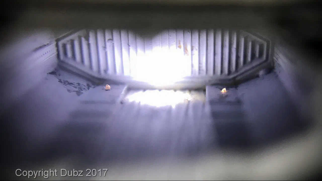
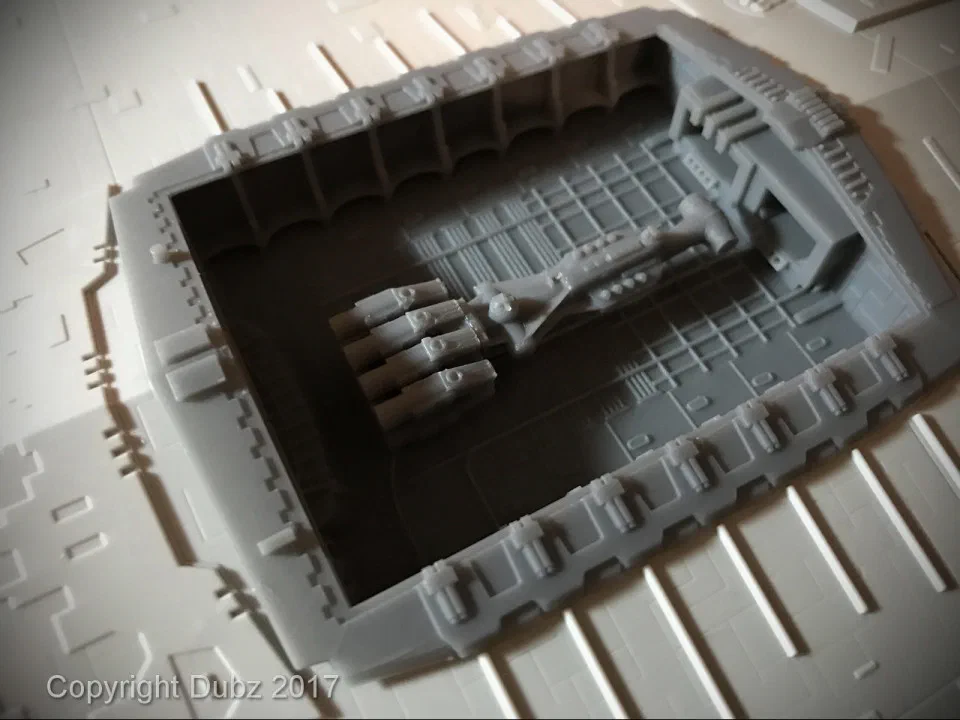
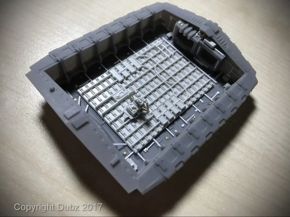
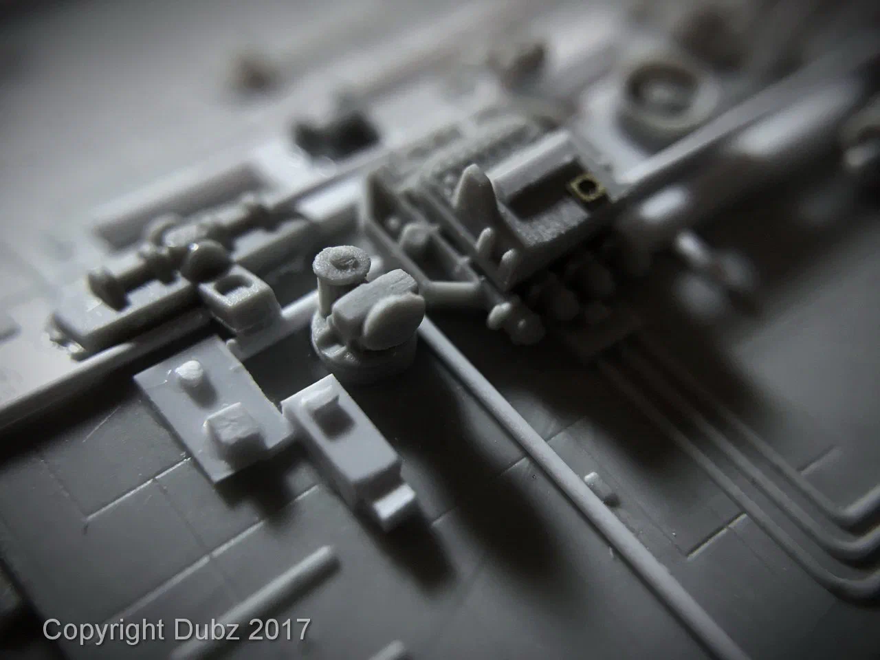
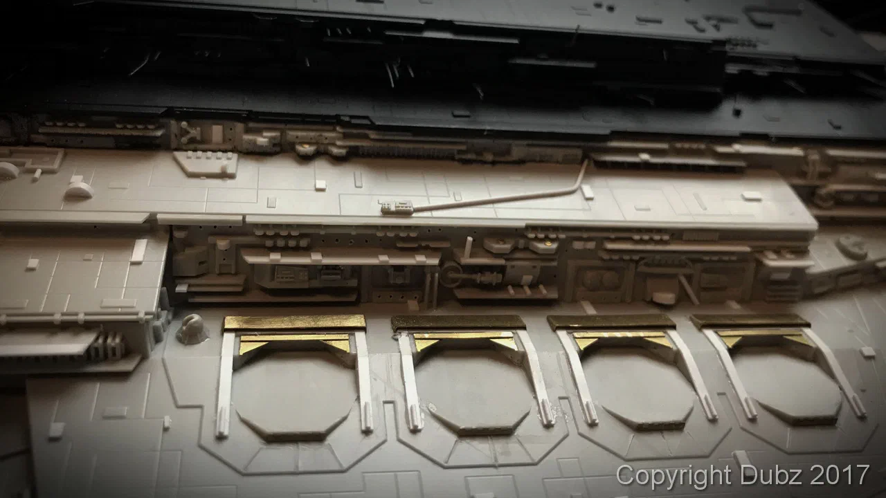
The main hangar bay under the hull is the Falcon3D replacement: a deep box full of structure, ready to be lit. The main guns and many smaller areas got more and more detail.
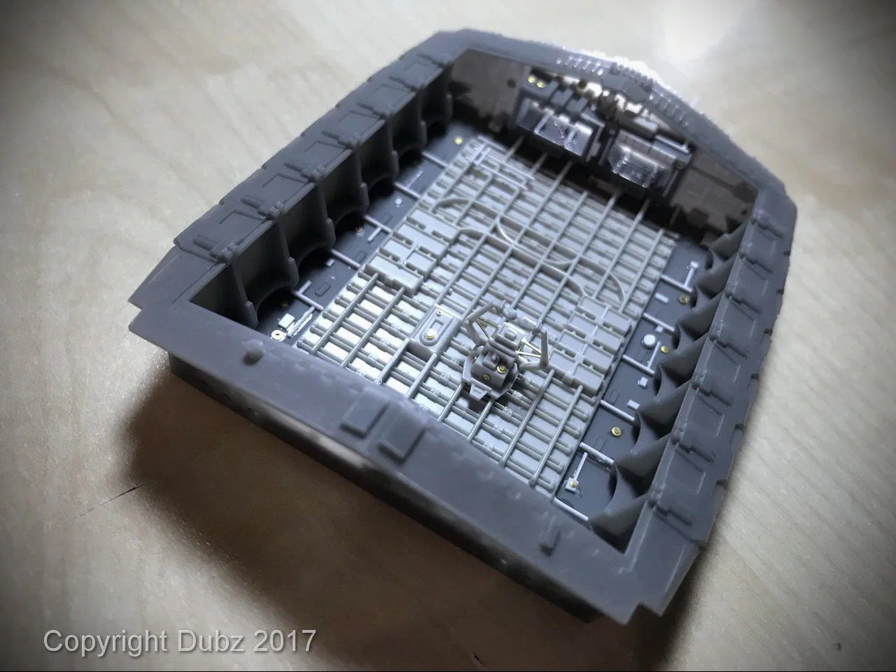
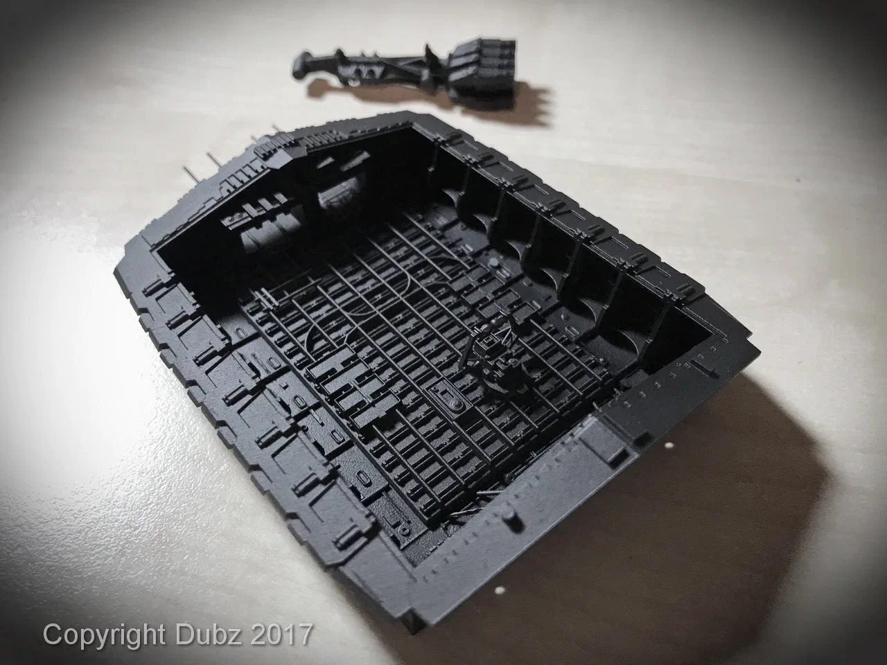
The rebuilt main hangar bay The hangar bay with its inner structure
The Falcon3D main hangar bay.
The hangar box from above The hangar box with its inner structure
The hangar box before it went in.
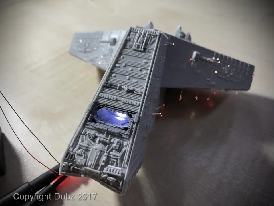
The hangar lit blue Detail at the shield generator bases
A first test of the hangar light, and the shield generator domes.
Greeblies on the upper hull The bow with added detail
More detailing on the upper hull.
The upper hull with greeblies Greeblies close up
Greeblies everywhere.
The upper hull with added detail
The upper hull.

Superstructure, trenches and a few thousand holes

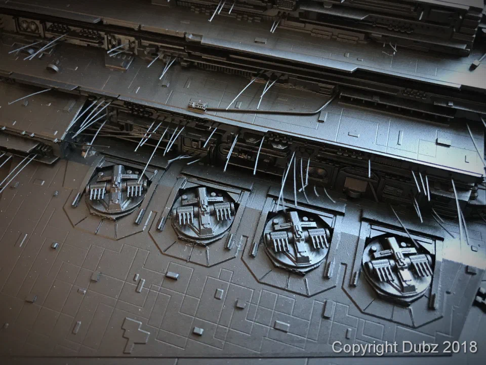
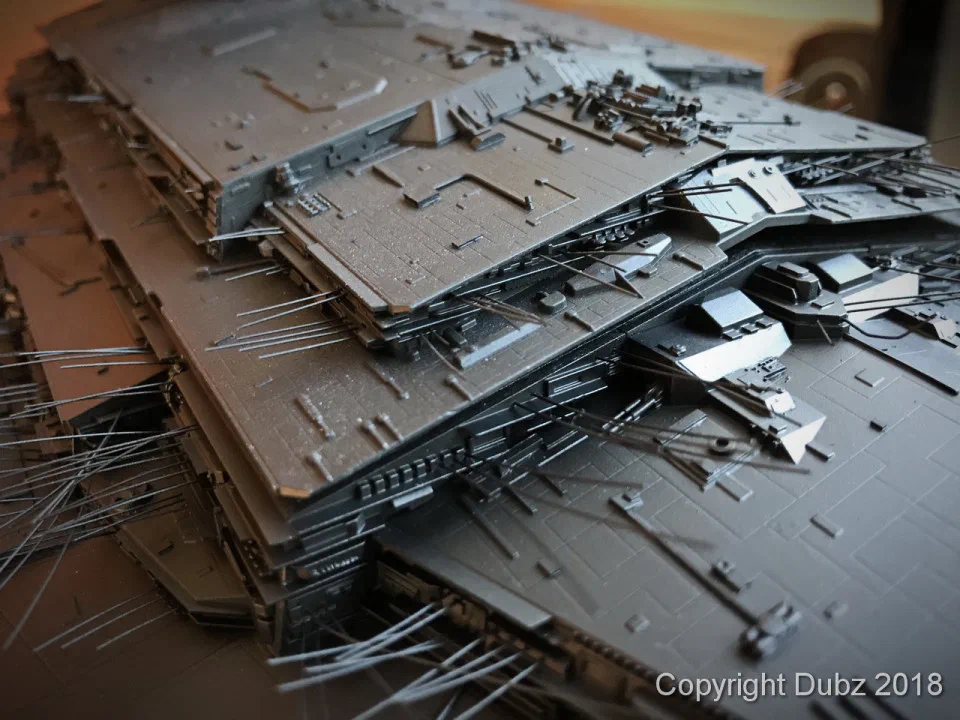
The upper superstructure and the bridge were finished and received a coat of black primer. Then came the part that defines this model: drilling. Most of the holes for the fibre optics are 0.3 mm, and there are a lot of them – in the superstructure, in the trenches and everywhere else. Along with the holes came greeblies in large numbers. And, of course, the obligatory accident.
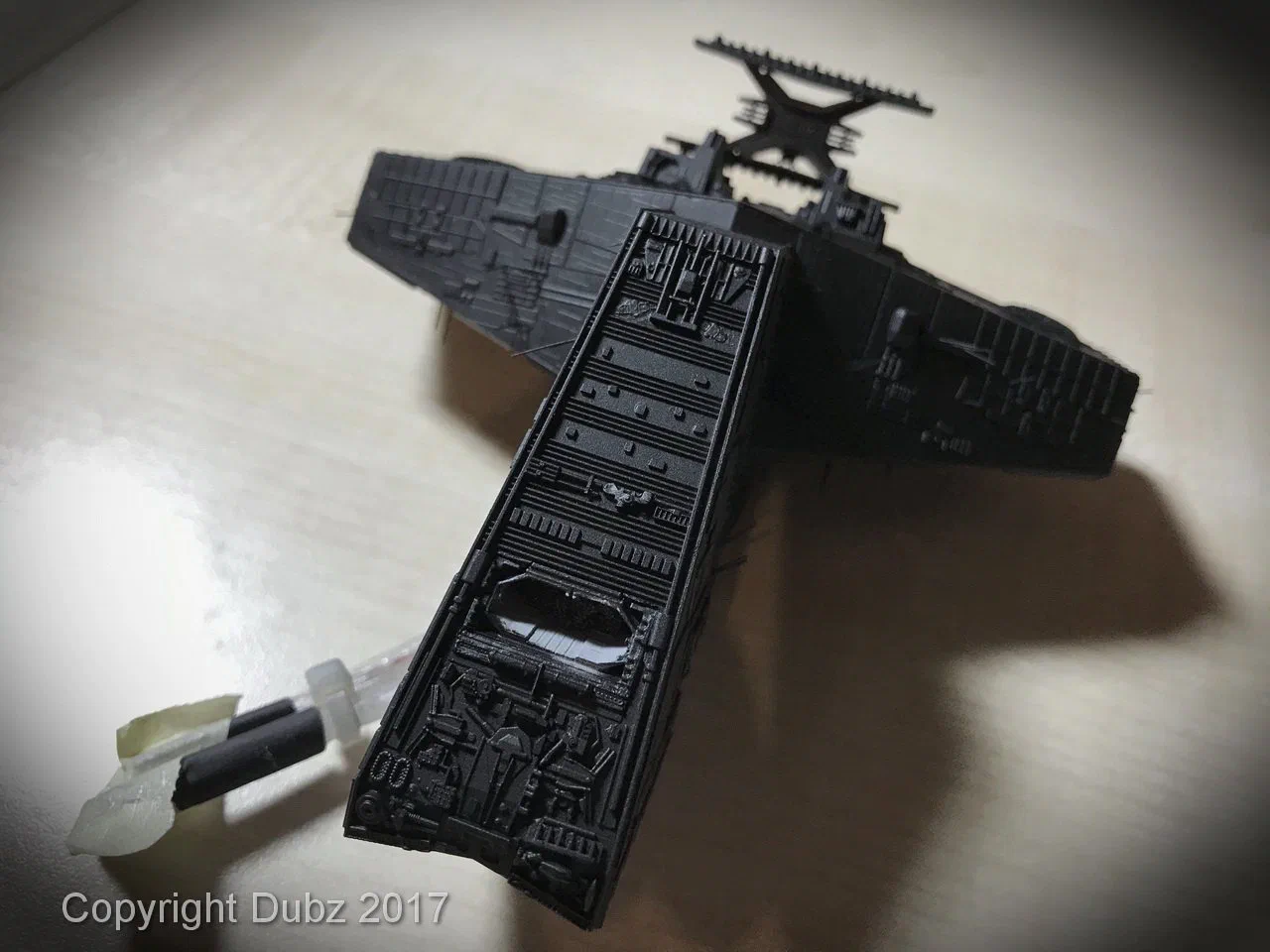
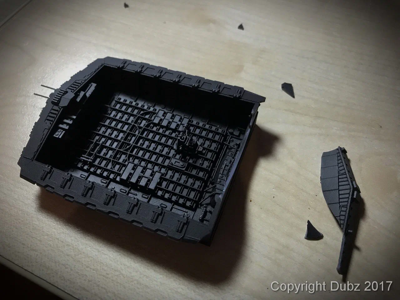
The superstructure in black primer The accident
Superstructure and bridge in black primer – and a damn accident.
The superstructure in black primer The superstructure layers in black
Black primer shows every flaw – and every detail.

The trenches along the sides were filled with structure, and the superstructure was built up layer by layer.
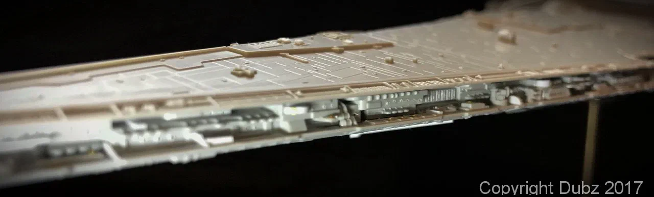
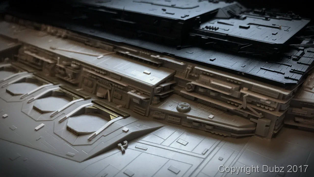
Detail in the side trenches The layered superstructure
The side trenches, and the superstructure taking shape.
Detail in the side trench The upper hull with the superstructure
Trenches and superstructure.
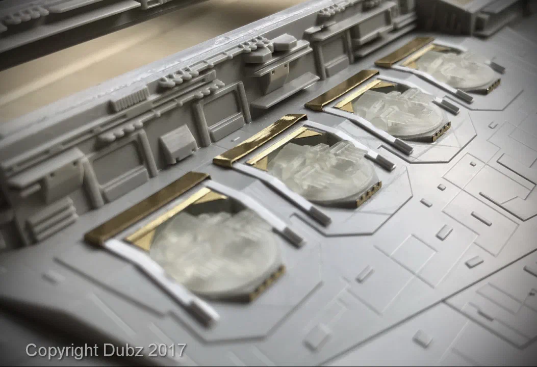
Brass-coloured details in the hull The layered superstructure from the side
Layer by layer.

The engine section

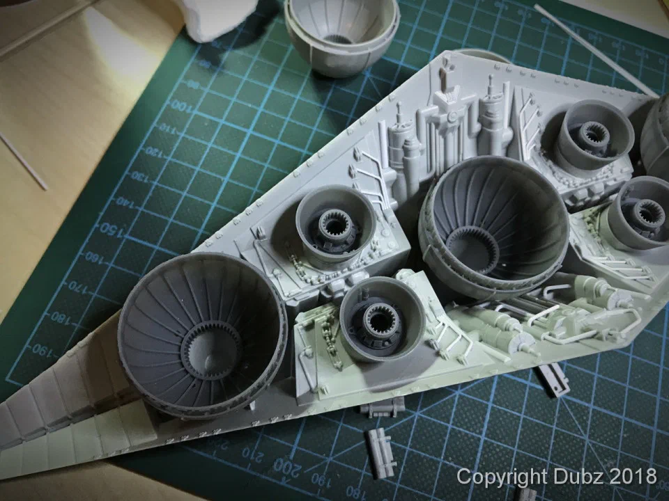
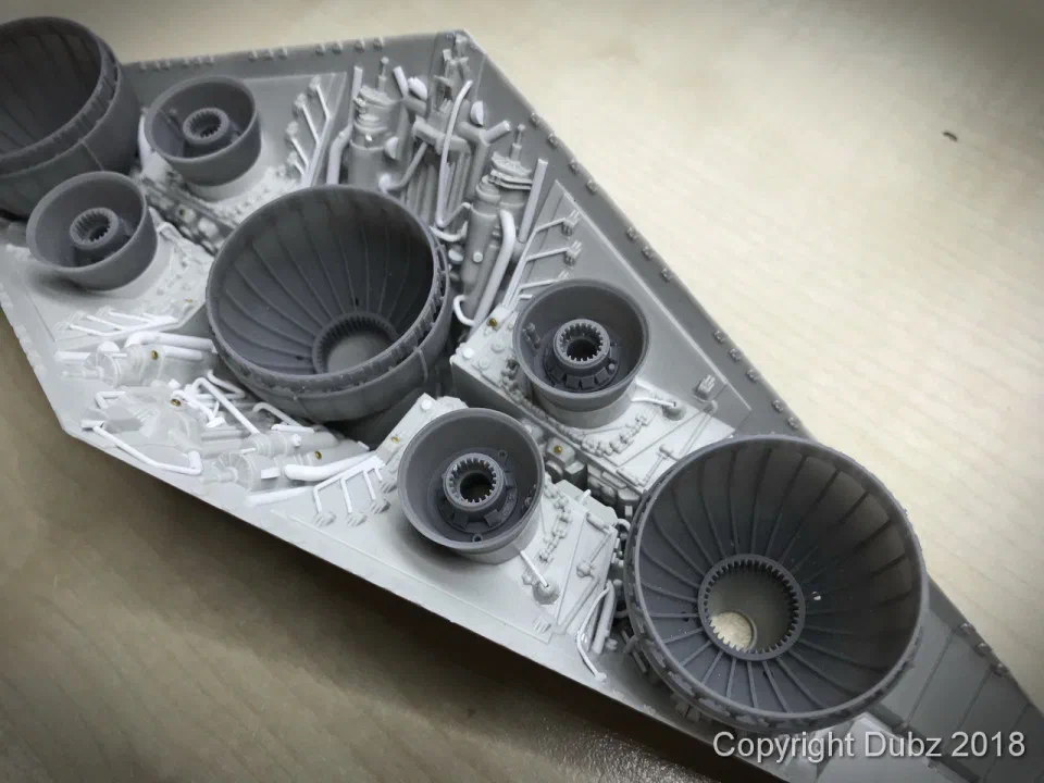
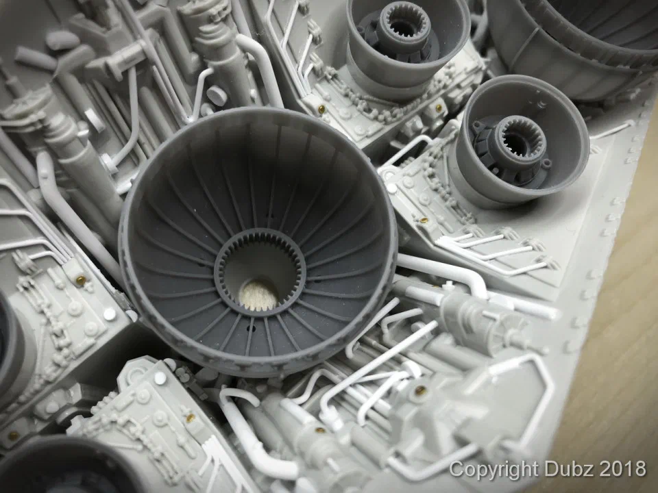
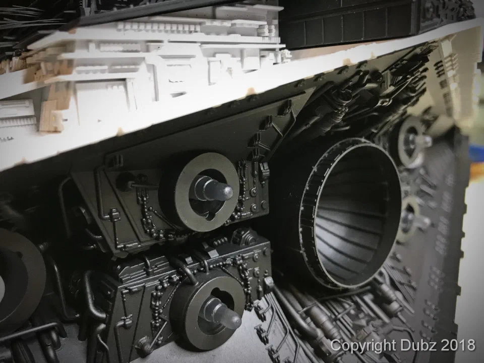
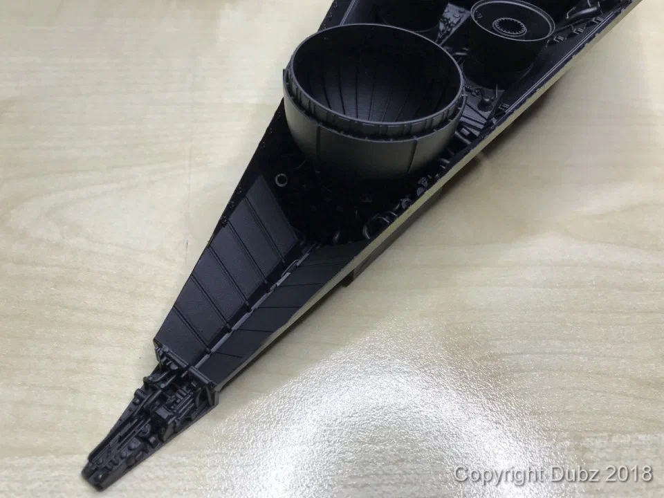
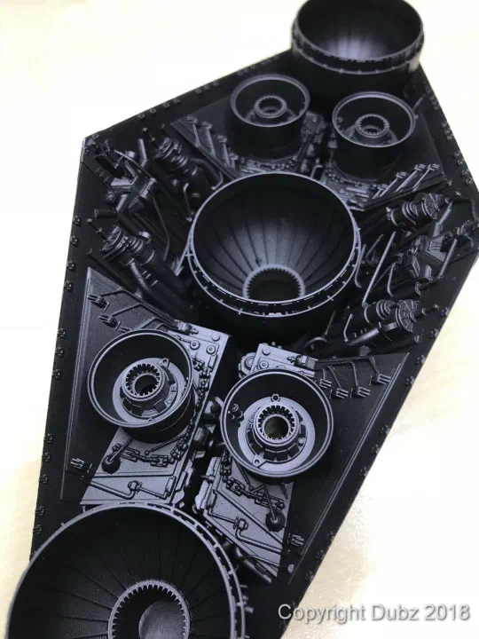
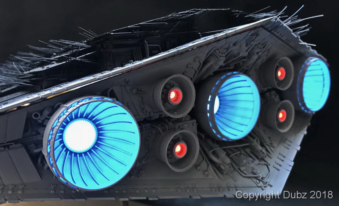
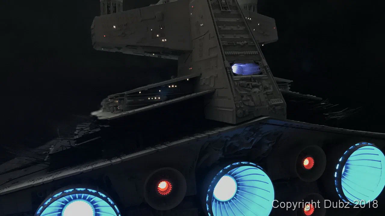
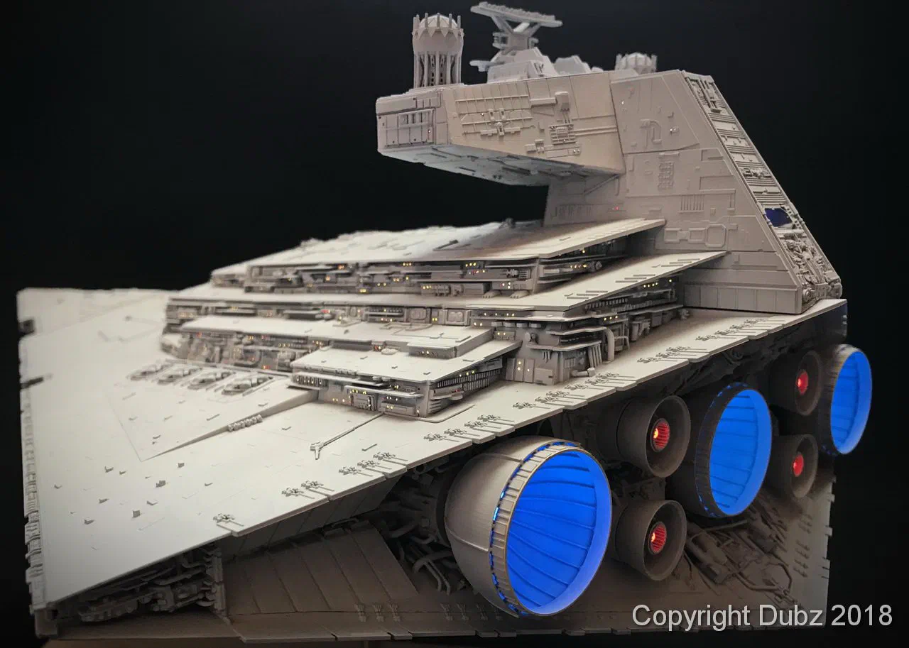
Next was the engine section – what I called the “engine section party”. The engines themselves and their lighting are Falcon3D parts; around them, the rear of the hull was covered with pipes and structures made of styrene rod. Only the thickest rod was bent with the help of a lighter; the rest was bent by hand or with pliers. The design of this panel is again a combination of the studio model, Invar’s work and my own ideas.

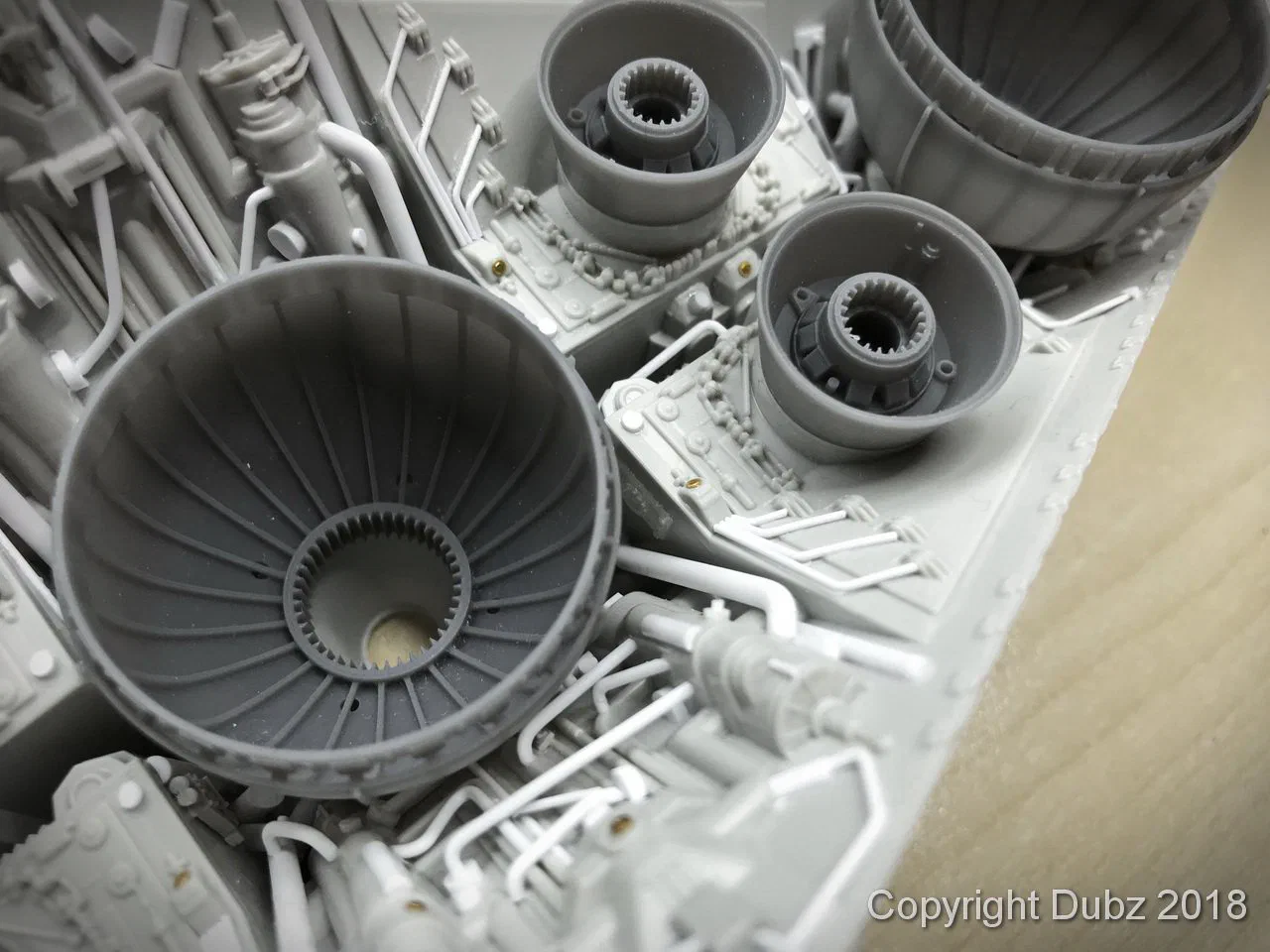
The engine section with styrene pipes The main engine with its surrounding structure
The engine section – styrene rod, bent by hand.
The Falcon3D engine parts The engines fitted to the rear section
The Falcon3D engines.
Pipes around the main engine The engine section in black primer
Pipes, pipes, pipes – and black primer.
The rear section in black from the side The rear section in black from behind
The engine section in primer.

Two hundred metres of fibre

Then the fibre optics went in. I have no idea how many metres exactly – my guess is around 200. With the fibre in place, all parts got their primer, the engine section and the lower hull in black first.
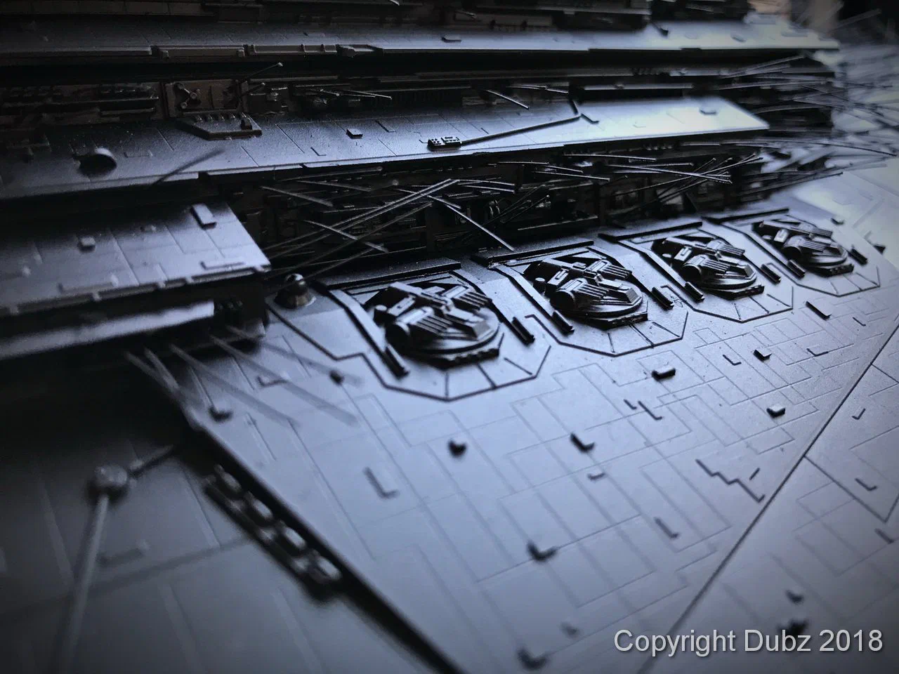
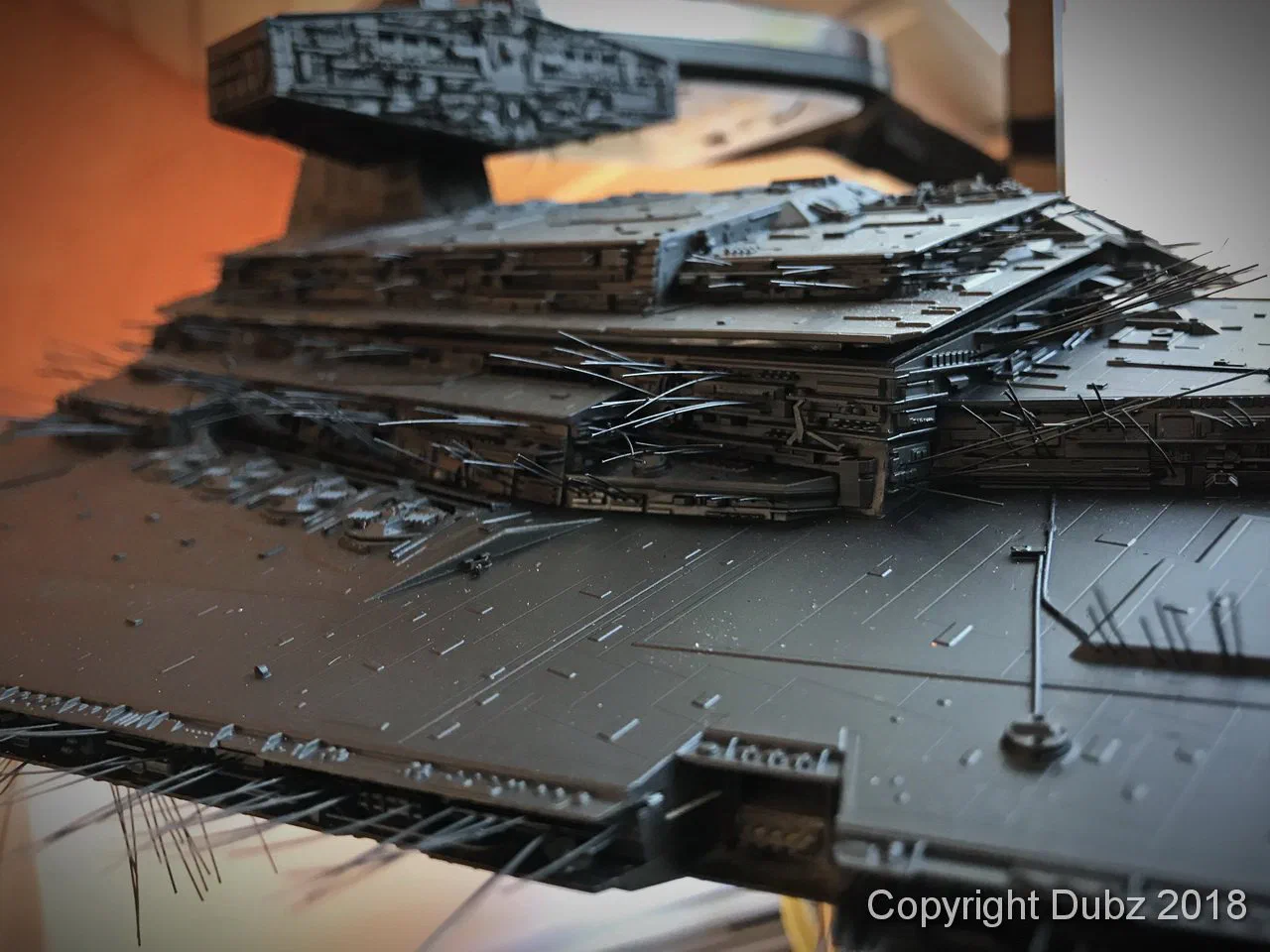
Fibre optics running through the hull The hull bristling with fibre ends
Fibre optics everywhere – and every end has to be cut later.
The hull from inside with fibres Fibre ends sticking out of the superstructure
Inside and outside: fibres everywhere.
The superstructure bristling with fibres
Before cutting.

The engine section, the hangar bays and the trenches were airbrushed next. Afterwards I cut the fibre ends in the trenches as flush as possible with a sharp micro chisel – which worked surprisingly well.
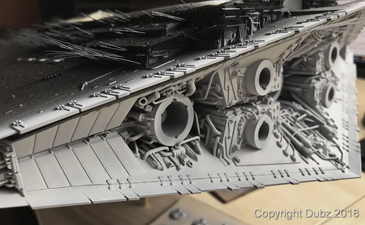
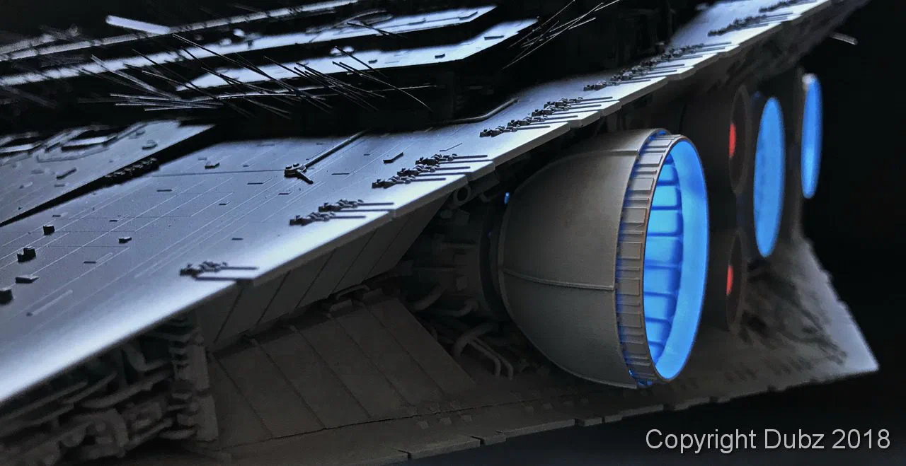
The airbrushed engine section The main engine lit in blue
The airbrushed engine section – and the first test of the engines.
The engines lit blue and red The lit engines with the hull
The engines at full power.

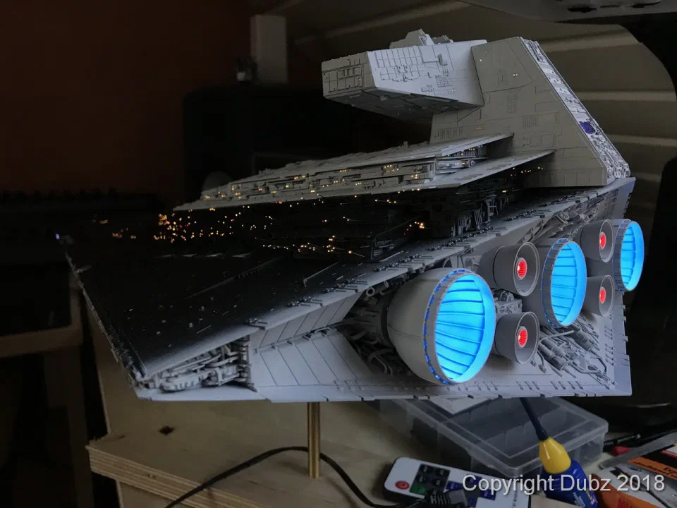
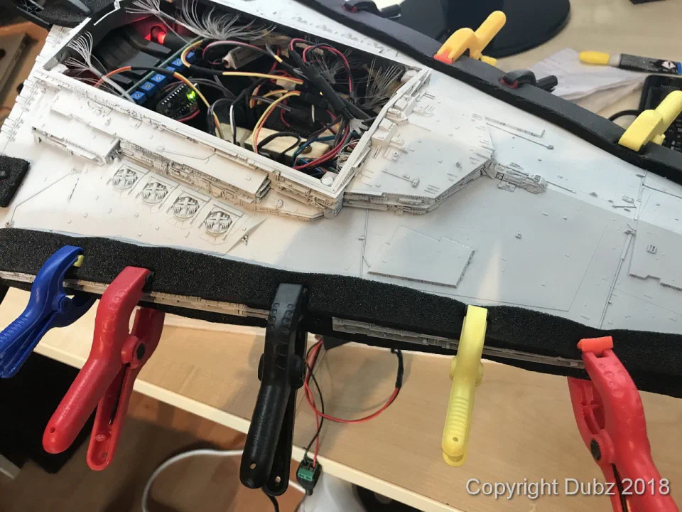
The electronics are hidden in the hull: LEDs, resistors and a small controller to set the brightness.
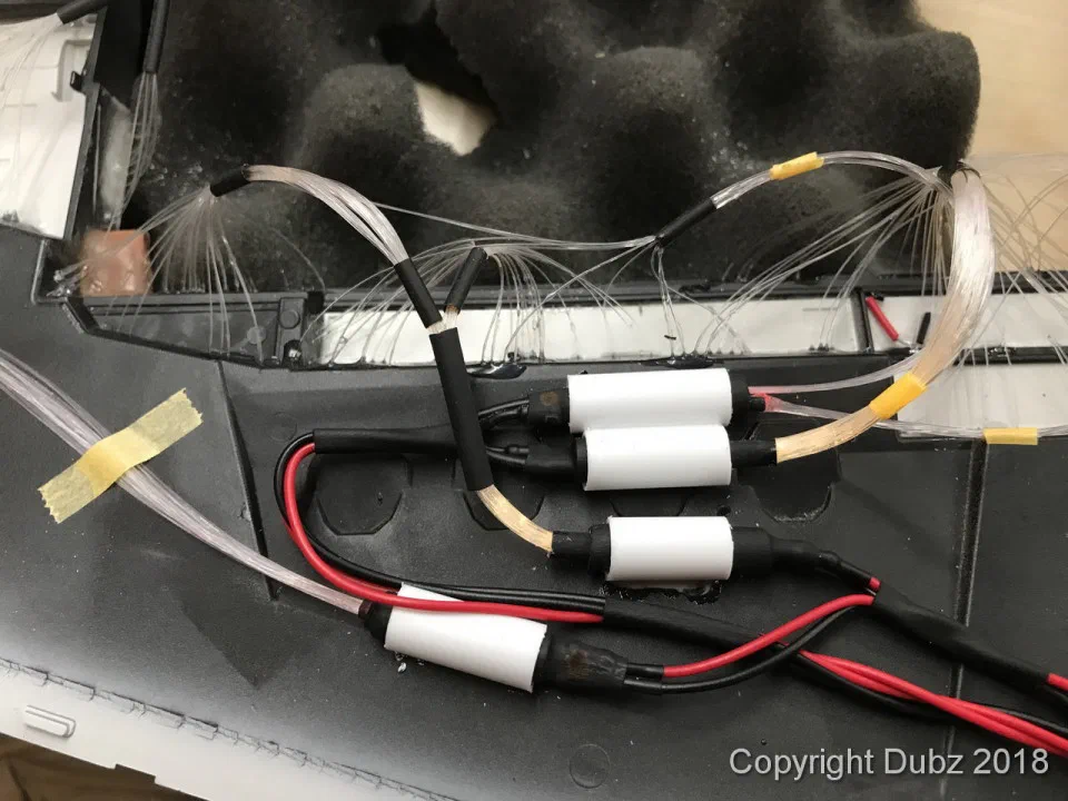
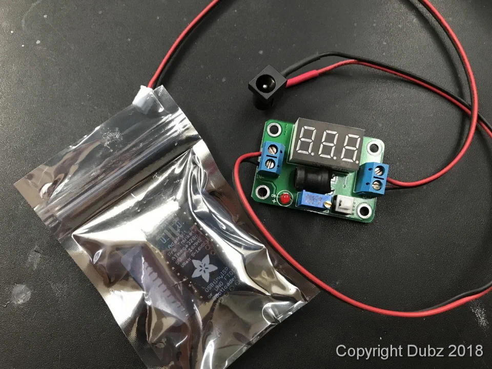
Wiring inside the hull The LED controller
The electronics.

Paint and light

The bridge and the upper superstructure got their first coat of paint. My main goal for the bridge was depth and shadow, and I am happy with the result. Then the lights were brought to life.
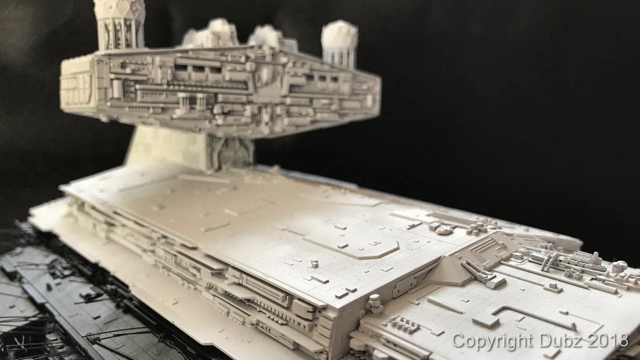
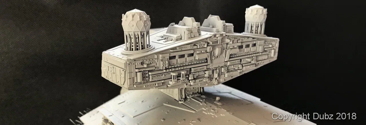
The painted bridge tower The bridge from the side with shadows
The bridge – depth and shadows.
The lit superstructure in the dark The engines and the lit hull
Lights on.
The painted bridge tower The superstructure after the first paint
The first paint on the superstructure.
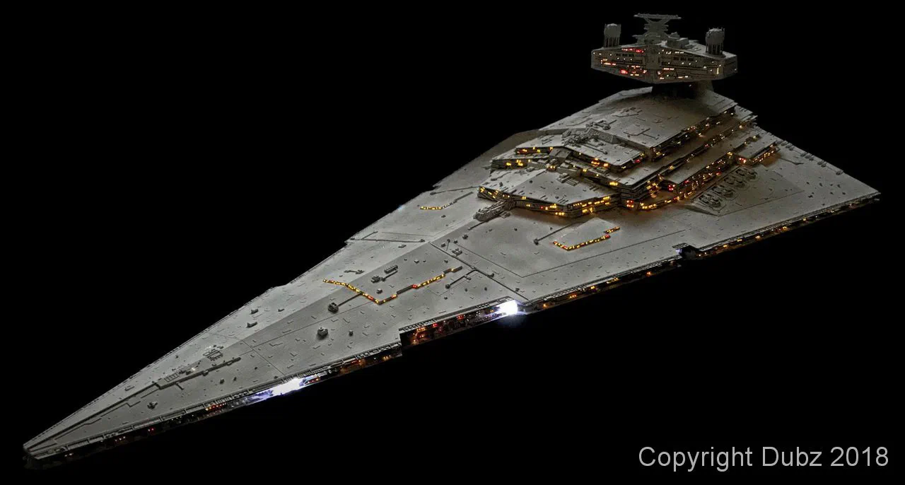
The superstructure with the lights The Star Destroyer in the dark
Light and shadow.
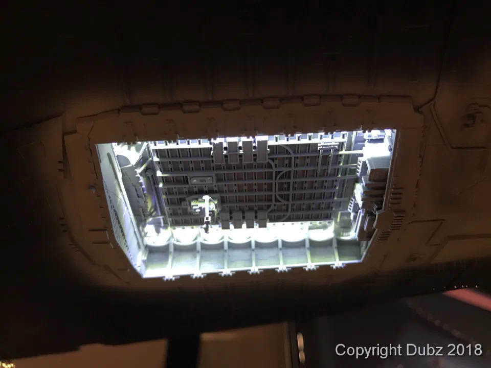
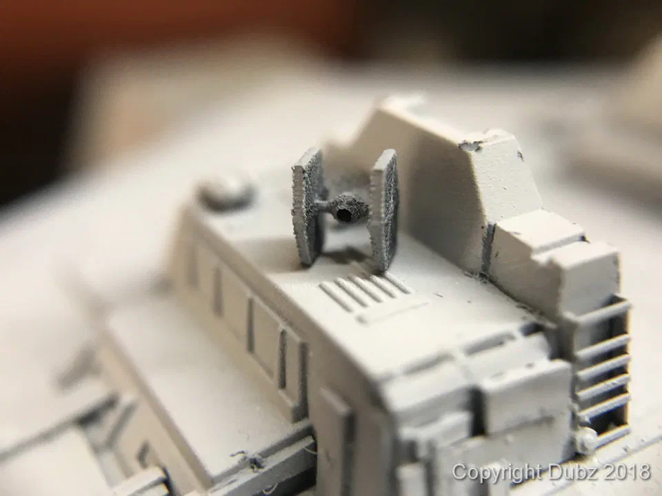
The lit main hangar from below A tiny fighter at the hull
The lit hangar – and a tiny fighter for scale.

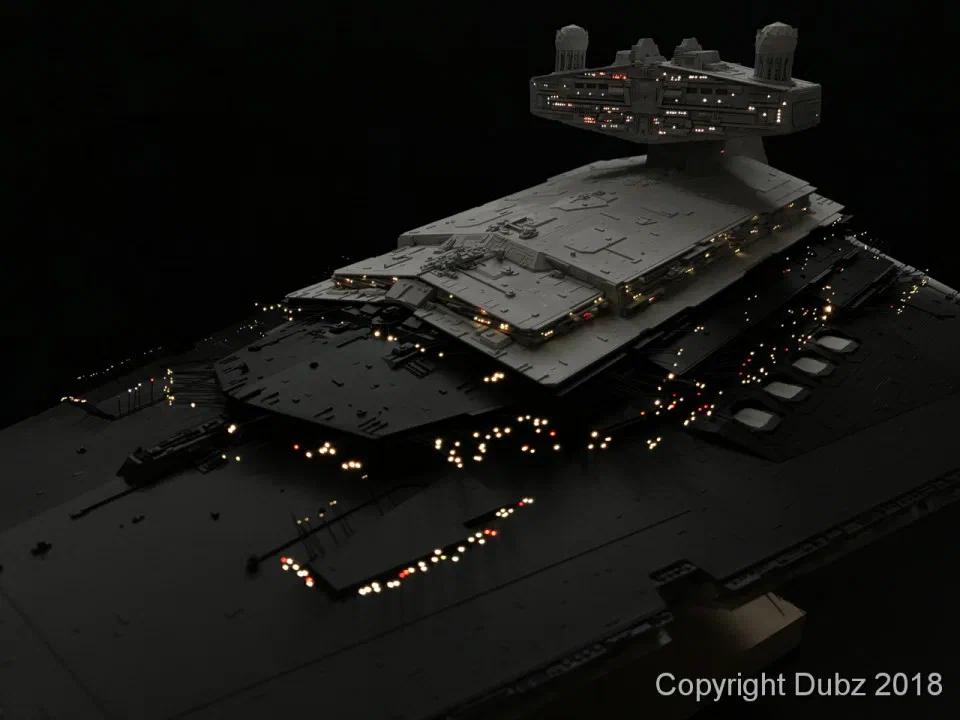
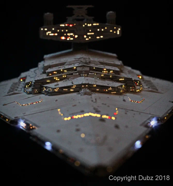
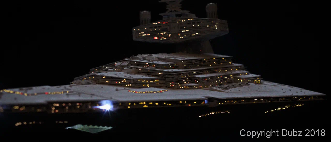
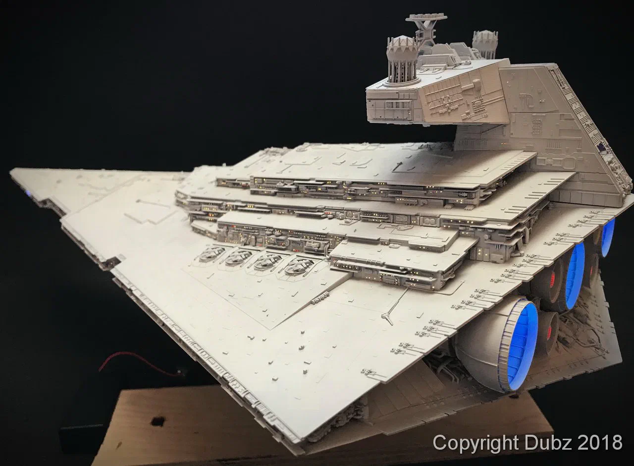
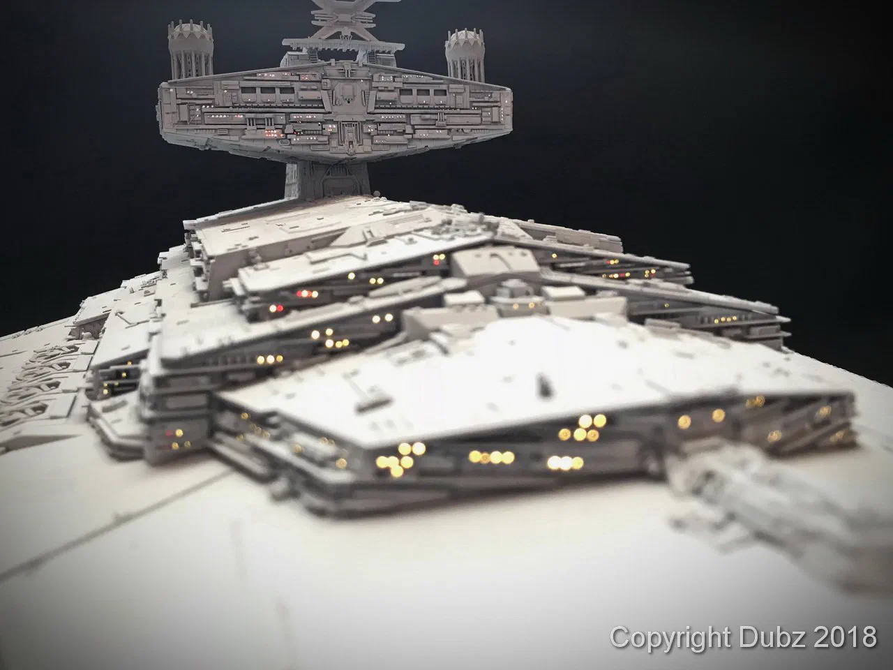
With the base coat on the hull, the Star Destroyer finally looked like one. A lot of small things were still to do, but the first test shots with the Canon showed that lights, colours and their positions worked.
The hull after the base coat The superstructure with the lights on
Base coat finished.
The Star Destroyer lit in the dark The superstructure with hundreds of lit windows
Test shots with the Canon.
The superstructure in daylight The bridge tower and superstructure
In daylight.
The bow seen from the superstructure The hull from the front, lit
Bow and front view.
The bow from above in the dark The Star Destroyer from the side in the dark
Night shots.
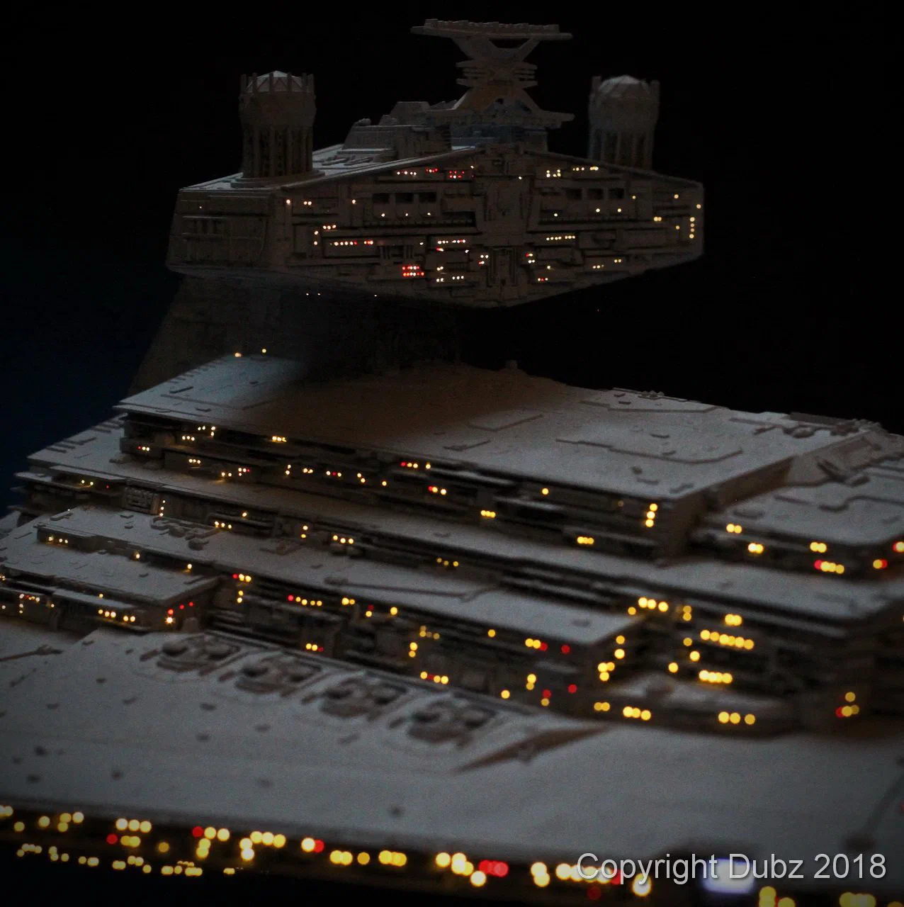
The lit superstructure close up The bridge and superstructure with hundreds of windows
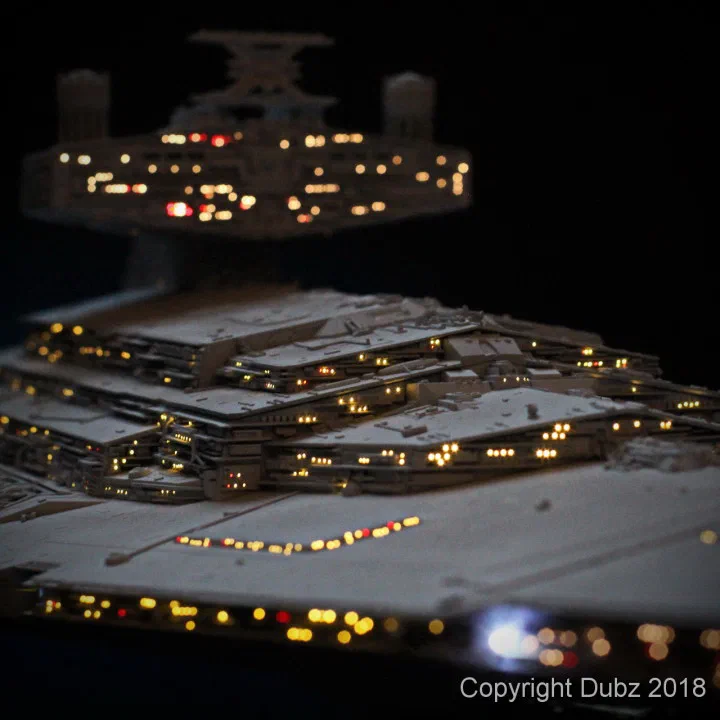
Hundreds of lit windows.
The superstructure lit, close up
Every one of these lights is a fibre end, cut flush.

The case

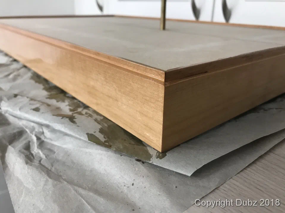
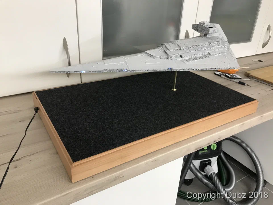
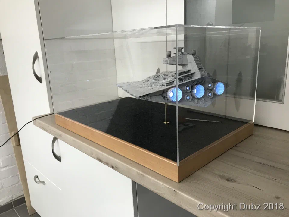
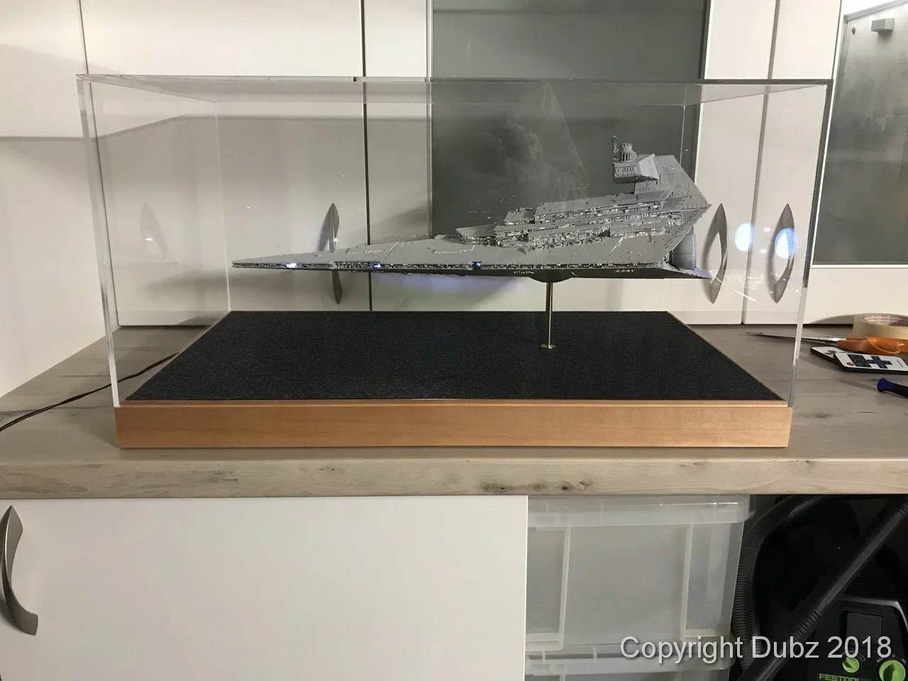
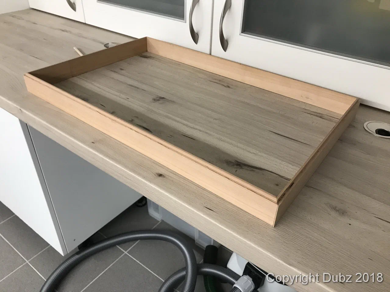
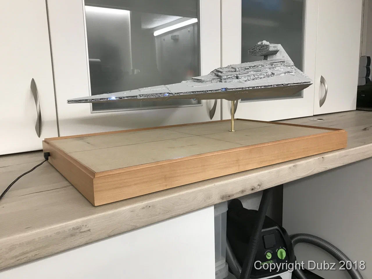
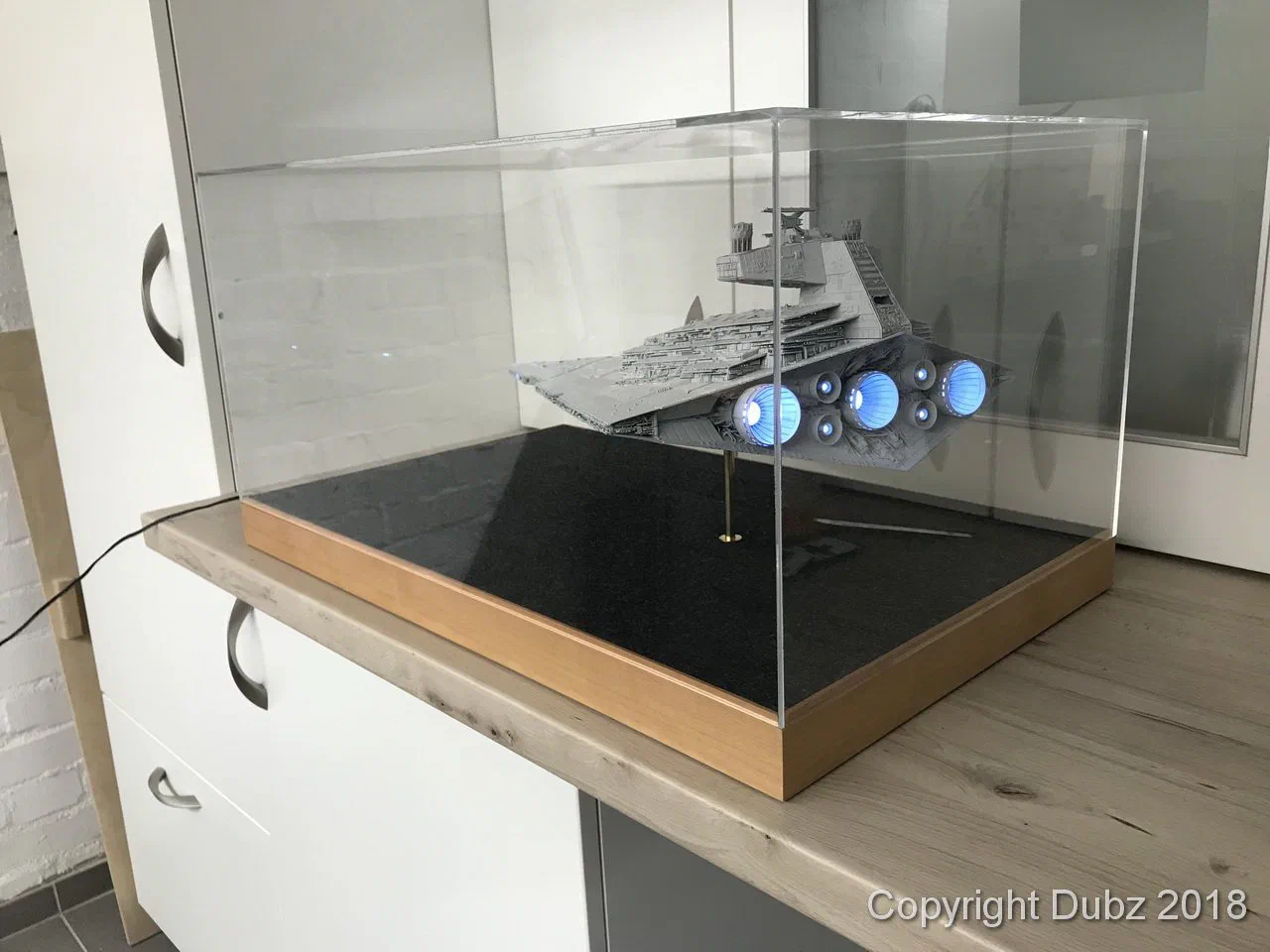
Before a move to a new home I finally glued the hull together – and then there was a break of several months. After the move I built the case: a wooden base with a brass mount, a dark textured surface and an acrylic cover.
The wooden frame of the case The Star Destroyer on the base
Building the case.
Gluing the hull halves together The wooden frame of the base
The hull glued together – and the base.
The Star Destroyer on the dark base The Star Destroyer in the acrylic case with the engines lit
On her base, and under the cover.
The Star Destroyer in her case
In her case.

Award

In 2021 the Star Destroyer won a Silver Medal at the online contest of the CMT – Centro Modellistico Torinese, entered as a work in progress.

CMT certificate: Silver Medal for the Star Destroyer The Star Destroyer in her case with the engines lit
Silver Medal, CMT online contest 2021.